• This forum is the machine-generated translation of www.cad3d.it/forum1 - the Italian design community. Several terms are not translated correctly.

equidistant points on an associate spline

sir--kris

Guest
Hello everyone,

I found myself faced with the need to add some equidistic points on a spline.
I tried to add them with the appropriate command in the sketch "equidistant points" and it does, only though I would need it to be something associative!
I would like to explain better: I would like that, once inserted for example 10 points equidistanziati on the spline and subsequently change the spline, they redistribute.
Unfortunately this does not. Catia divides them according to the length that finds when I insert them, but after it does not redistribute them.

I also tried to bypass the problem by inserting points outside the sketch with the "point on curve" command and giving it for example a percentage rate from the beginning of the spline at each point, but also in this case, if I change the spline, these do not redistribute, in short they are not associative!

Is there a command or a way to get this? I don't have the freestyle module, which is missing something in there?

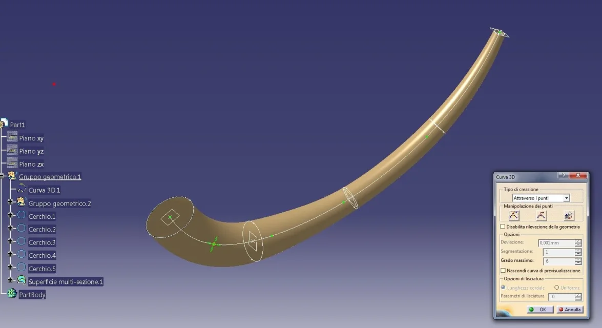
my real final purpose is to insert circles centered on a spline (the latter free to be modified) that however have the equidistanziati centers, obviously equidistanziati on the arc length not minimal distance. I tried to put a quota on the arc of curve, but hamè does not, ie it takes the minimum direct distance, or at the max the whole spline and not the center of the circumference.
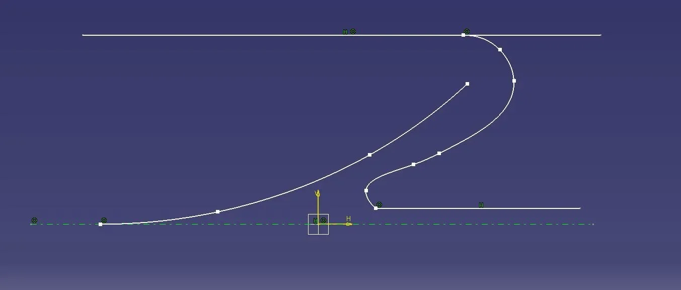
I also thought of making so many small splines (of equal length) between one center and the other of the circumferences and giving it the bond of parallelism to the point of contact between them and I can...but then if I go to change the spline by dragging the points ... the pc gets in trouble and slows everything, sign that behind is making an absurd computational effort... and I can no longer change the spline at the end!
the pc is the workmanship (a workstation also suitable for axioms of 3000 parts) so I think that more than the pc is wrong the approach to solving the problem.

What do you recommend?

I attach a photo to make the idea....

Sir...screenshot.webp
 
Hi.

I did not understand well what you want to do, however to maintain equidistant points and plans I do so (in generative shape design environment):

1) I create spline in a sketch

2) I go out of the sketch

3) menu-insert-wireframe-repetition of points and plans, selections "with extremes", from the number of occurrences and (if you need) even the plans on which to create the successive sketches of the circumferences.

if you change the spline, points and plans go after him equidly (but the number of points remains the initial one).


Let me know.

Hi.
 
Hi, gianni,

Yes, yes, the number remains the same, as long as they remain equidated to vary the length of the spline.
in my case the circumferences are all in the same plane, that is the sketch of the initial spline.
However tomorrow I try as you say in generative shape design, I think it can work equally.
I'll let you know.
Bye-bye
 
Hi.
I add, in case it's your interest, that sometimes it's best not to use sketches.
I know that they are the first thing they teach you at courses, for many things they are very comfortable, but they represent a discontinuous environment compared to 3d and with some limitations.
a limitation that, to me, seems obvious is the impossibility to see in real time the update of the 3d whenever, as in this case, you have a spline on a sketch and go to change the same.
for this, many times, it uses the "working support" . to define it:
1) Select the plan you want to work on;
2) tools/grid/work on support;
3) a window opens, define the point of origin (better a point defined by you) and first direction (even here better a line defined by you) and ok;
4) in the geometric tree you have a "cut" with "working support" and your "working support highlighted in red. It means you're working on that plan. If it weren't, select your interest, tast dx, support.object at the bottom, "set as current".
5) always from here, also select the "get feature on support". in this way every geometry you create is created on the work plane;
6) At this point you can work on the 3d as with a sketch, with the advantage of having all the 3d commands available (spline, circles, rays, points).
7) also tries this way of working. You'll see it has its advantages. in many companies, especially where parametric surfaces are made, they use it instead of sketches.
 
Good morning gentlemen,

Then:
- I tried as you said gianni55 and actually the points redistribute in an associative way, but for my final purpose there is no good, as I should always go out and go back to the sketch to be able to change the spline.
- I tried as an expat reader (nice trick not to get into the sketch) but also this case is not useful to me, as once a spline is inserted I can not have control points from where to take it and drag it "continuous". The only way to change it is to change the points from where it passes. I want something fluid...plastic.

I try to explain my wish/final purpose:

premise: Think of being in a semisection of an axisymmetric duct, which moreover has a central soul.

I need to draw a conduit with a certain law of expansion. the problem arises when dealing with mixed flows (and not totally axial or totally radial).
In practice, in this case, in addition to imposing the law of expansion, I must also impose "compensation" on the varying distance from the central axis (radial compensation).
My idea was to create so many circumferences that have their centers lying on a spline (which in practice represents the average line of the flow) to impose through the functions the law of expansion between the circumferences (to simplify I made that the next is 95% of its previous) and to impose (always in the same functions) the compensation factor dependent on the distance of the centers of each circumference from the central axis. This would basically create me some nice circumferences that "tangendoci" above would create me the inner and outer profile of the conduit.

In practice I find myself that .... always in the same sketch..... I "plasmo" my good spline continuously dragging the control points of the same, all the centers of the circumferences follow me below and the diameters change depending if I approach or flood from the central axis.
Unfortunately, however, there is a detail missing, so that all the laws imposed are valid I must have an equipment between the centers of circumferences.......ecco....it is exactly what I can't do on this caspita of spline!

How can I do that?
I have to think that to have a continuous change.... I have to... or be inside the sketch or maybe always out.
In short, avoid getting in and out of one or more sketches!

I'm sorry, the papyrus, but it's really an exciting puzzle.

ps: I have subjected the same problem to a guru of nx....(official teacher certificate)....though....never in that environment you can manage! in nx have the nice that the equidistanziati points are associated with the varying of the spline, but they have another problem, you can not impose functions of variation using as given a quota "reference" and or a "measure" on a circumference.... but vague...this is another speech.

Hello everyone
 
1) I hope I don't let you do the "pee spin" for nothing;
2) creates the graphical law of variation for circumferences (law);
3) creates a surface with a sweep and as axis the spline;
4) creates a spline offset on the sweep;
5) apply the law to the offset;
6a) creates as many circumferences as you want. Each of them, even if not equally spaced, follows the profile with the law you have defined.
6b) always inside the sweep command there is the command (third option=circular sections) "central curve and 2 corners": give the spline as thorns and the offset as a guide curve. angles 0-360.
I have to try calmly... but I'm afraid it's not okay, as I go in and out of various sketches if I didn't get it wrong.

thanks in the meantime
 
I have to try calmly... but I'm afraid it's not okay, as I go in and out of various sketches if I didn't get it wrong.

thanks in the meantime
I have a question for you: can you define graphically, in case your axis is represented by a straight line, the performance of your function/expansion with respect to that reference?
 
Hi.

also follow the reader tip, but I think you can also try to get a "spline" to change continuously, using a 3d curve:

environment: shape-free style

menu- insert-creation of curve-curva 3d

You create one as you want on a floor, like a sketch, but you don't have to go in and out, and the points will move all the time.
this type of curve is also controllable through points, or through external points (very easy to handle for smoothing)

(or you can move it in the other dimension in 3d, only then you have to use more shortcuts to edit it in the right direction).

obtained the 3d curve, also falls into the environment that is more congenial and completes the work.

Let me know.

Hi.

years ago
 

Attachments

  • 1.webp
    1.webp
    64.1 KB · Views: 5
I believe and hope I understand your problem
In my opinion, you must
use the knowledge pattern module, and through this
environment, you will create a (n°) variable points
along your reference thorns (better designed in the environment
free style, as gianni suggested)-

in the appropriate table you will appear using the form
you will have to declare your variables;

let c = curve = your thorns
let pt = point -= the points you want to get
) = integer= the variable number of points you set

and subsequently through the created function created homodified bytum and expression
for i while i (equal or lower or greater) of your numerical value (representing the number of points)
you will obtain, using the function of points on curve in percentage value (ratio) ,
your point list

always within the same environment, you will generate a list of plans
(normal to your thorns) with origin in the points of the list previously
obtained

You should at this point create a series of numbers (which will represent the radius)
of your circles) closely linked to the radius of the initial circle and the percentage of
Single update (95%) and variable number of dots on thorns-

Now, using the list of points, the list of plans on which the circles lie,
and the list of numerical values (lengths) which will determine the radius,
you will create circles, which will be grouped into a list-

finally, using the list of curves (circles) and your thorns
You're gonna make the loft your conduit.

of course, you should create parameters related to;
- (integer) number of points
- (length)Initial radius value
- (real) percentage value of radius update

(to also consider that the value of your initial circle may be
directly related, through appropriate formulas
to the rapport between the length of the thorns and the number of points, updated in multiplied by
your coefficient (real 1)-

es (3000 mm/10 *real 1) = radius first circle
where
3000mm is the length of thorns
10 represents the number of points on thorns
real 1 represents an increase or decrease value
of the report obtained )

at this point varying, or the number of points, or the value of the radius,
or, manipulating the thorns in its control points, you will have the update of your duct-

I know that this is not very simple,
especially if it lacks the basic preparation of processes related to the knowlwge pattern. etc. ,
but, unfortunately, at the moment my catia is not working...
I'll try to put the example in the first place, as soon as I have
solved problems with my program-

In the meantime, since, on the other hand, the fathopper module of rhino
I would like to thank the rapporteur for his work.
with greater disgrace than catia, for the moment I attach the files in 3dm and gh
and some explanatory images. . . -
I hope someone among you knows and uses rhinoceros and fathopper
will find the definition, similar to the above,
even if performed on a nodal system (gh)
instead based on scripts like catia-
I hope I have contributed to the resolution of your problem
greetings
to theCondotto parametrizzato.def GH-.webp
 

Attachments

as mentioned in the previous message, now that I have solved the problems
with my caty ", taking advantage of the weekend,
I send you the file and some pictures, clarifying hope, of
my personal solution of the problem "conduced"

Imperative premise must be set in the appropriate
field options/parameter /knowlwdgwe/knowlwdgeenvironnement
in the way I enlighten you with these images1-Set-UP-Parametri-Knowledge.webp2-Set-UP-Ambiente Knowlwdgw.webp3-Set-UP-Ambiente Knowlwdgw.webpI recommend that when you are in the field knowlwdgwe environnement,
appropriately set the path that asks you where to save
i type custom e le path del knowledge....

I suggest you indicate the following routes:
-programs/dassault /bin/resources/ knowlwdge/ type custom
-programs/dassault /bin/resources/ knowlwdge/
This will allow you, in the future, when you are more prepared,
to also use the resources pwc udf part template etc. etc. in the environment
knowledgepattern and knowledgeadvisor.......

in the attached file I created an editable spine(curva3d) on which
insert a variable number n of points... .
(to change the number of points edit the parameter npt.... )
at this point in the relationship field you will see that the indicating icons
iknowpattern will show the active update icon, so
Therefore update the sequences all and you will see that the entire construction
will be updated. . .
this because I deliberately set the manual update option
in the field of knowledgepattern training
I did it because it is easier to edit the 3d curve in the environment
free style-
Below are some images related to scripts created etc.1-Script-Point on spine.webp2-Script-Planes on Point.webp3-Script-Circles on Planes.webp4-Script-Loft Condotto.webpI hope that the example will be resolute to the problem,
and that will serve those of you who want to deepen
these aspects of automation that it offers-
greetings
to the5-Struttura KnowledgeTemplate.webp
 

Attachments

I have a question for you: can you define graphically, in case your axis is represented by a straight line, the performance of your function/expansion with respect to that reference?
Yes the axis is a straight line, it would be easy... how to draw a square....or a cubica!

What's your idea? :redface:
 
Hi.

also follow the reader tip, but I think you can also try to get a "spline" to change continuously, using a 3d curve:

environment: shape-free style

menu- insert-creation of curve-curva 3d

You create one as you want on a floor, like a sketch, but you don't have to go in and out, and the points will move all the time.
this type of curve is also controllable through points, or through external points (very easy to handle for smoothing)

(or you can move it in the other dimension in 3d, only then you have to use more shortcuts to edit it in the right direction).

obtained the 3d curve, also falls into the environment that is more congenial and completes the work.

Let me know.

Hi.

years ago
Uhmmm guys checked and I don't have the free style module at work. It's probably what he would do to my case for freedom issues.
cmq gianni 55 your design, is not exactly what I need to get....to make you understand I make you a draft (indicative of course):
 

Attachments

  • Cattura1.webp
    Cattura1.webp
    13.9 KB · Views: 2
  • Cattura2.webp
    Cattura2.webp
    43.1 KB · Views: 4
alpole, I thank you so much for the things you made me learn by reading your messages...for me they were new things, which I never had to use.

but also in your case, it is not exactly the type of pipeline I want to get.
refer to my message, which precedes this.
I posted a section of the conduit (a portion of the conduit, let's just say the section of the conduit concerned).
Pretend that the flow turns from left to right... widens on the central cone....and once it arrives at the bottom...ruota...and retracing the wall (the interior of the first cone, which should therefore be a wall common to the two macroambients) back a bit and rejoins the center....and then rejoin in the central small tube.

here in this flow I would like to impose a function of expansion (lower pressure and increase of speed) continuous according to a function....that is...maybe a square.
the complicated part, as you can understand, is because it is a mixed flow (axial-radial).

Perhaps all of you have been drilled by the circumferences that I drew in the first messages....it because I specified they were in the same plane and not perpendicular to the spline.esse i have drawn them as "invilusion" of the flow within the duct (in the semisection as the one inserted in the annex of my message that precedes this), with the hope that they had helped me to define the various walls of the duct in short.

I hope I've been clear, if I were, ask me more info.

Bye, guys.
 
actually, looking at your last drawing, I had misunderstood completely
the question... .
and let us make it clear that I am not an expert in the field;
but, always if I have not yet misunderstood the question, if what you want to do
approaches the attached schemeCond.webpthere are to my say some parameters that you should fix:

- scope of conduct and speed of the incoming "flow"
- scope of conduct and speed of the outgoing "flow"
- form and dimensional data of the incoming section
- shape and dimensional data of the output section
-disputes between the various "passages" between the entry and exit section

already fixing this data will give you values that you can exploit to create a
sketch (like what you will find in the attached file) in which, using
relations between the various parameters, you can finally give a form to your duct,
otherwise... we stay in the "fried air" field

I can tell you that if you provide data to base on
the "research", you will find almost certainly, people with a consolidated experience in the field
who could help you
Let us know
greetings
to the
 

Attachments

actually, looking at your last drawing, I had misunderstood completely
the question... .
and let us make it clear that I am not an expert in the field;
but, always if I have not yet misunderstood the question, if what you want to do
approaches the attached scheme
the type of duct is reset.
there are to my say some parameters that you should fix:

- scope of conduct and speed of the incoming "flow"
- scope of conduct and speed of the outgoing "flow"
- form and dimensional data of the incoming section
- shape and dimensional data of the output section
-disputes between the various "passages" between the entry and exit section

already fixing this data will give you values that you can exploit to create a
sketch (like what you will find in the attached file) in which, using
relations between the various parameters, you can finally give a form to your duct,
otherwise... we stay in the "fried air" field
to the
In theory, I could give some parameters, but for me it is not important to be able to build a single already beautiful conduit sized for a single case.

I would like to be able to impose the laws we talked about before and that everything is (as you rightly asked alpole) parameterized by simply inserting the entry section.

so much to understand if you want me to give you a data, pretend that the entry section is 100 cm2(to simplify), the law of expansion defines you, but that it is not by chance, that it is a square...logarithmic. - What?


hello and thanks to all for your messages
Sir...
 
Sir-kris
in the file that I attach to you, I hypothesized a connection between ducts
with different input/output sections, governed by parameters,
and a length between these two sections, also governed by
parameters-
in the first case
with a sketch I determined a graphic percose to create a
constant law to scale between the two sections-
I applied this law to my ideal line (which represents the distance
between the two sections). .Schizzo per definizione Legge 1.webpsupporting me to the parallel created by the law above, and creating
ad hoc planes and line of reference, I drew references (published)(lines and plans)
to create the spline that represents the trend of the connection-Percorso condotta.webpapplying the law to this new spline I built two parallels that
represent the edges of the connecting duct. . .Legge-1.webpthis definition and reusable and totally parameterized
therefore applicable to different distances and sections... .
Moreover, if you want you can change the law, varying it from constant
to all you want, instead of using mathematical language,
sometimes complicated and not at the reach of all, the fact that
you can set a sketch and then build your path by customizing it
is a great advantage.

in the second case
I have travelled another way, to build a law
derived from a mathematical formula, so I created law 2
with the flyout data of the feature law that provides a set of parameters
to be used specifically, as well as mathematical language
in this case I used an expression with cube values on my reference
x
more properly,
= 25 +(20*x*x*x*x)*-1
Where:
y= param real2
x=param.real1


so you will see illustrated the two cases;
the first species, the one with the construction (manual of the graphic law) by means of a sketch
and the most conceptual one with the insertion of a formula-

the result is not different, apart from the law set, indeed, perhaps with the manual approach,
with variations on the values of the sketch quotas that determine the
This is the mathematical equation solved, complete with domains on x and y etc.etc.
the live mink of function is facilitated, while often with a mathematical expression
We do not know exactly what we will build until we see the result. . .
in your specific case, with a very strange connection path for me, once defined
the path, you can apply any law and get your conduit
precise that I am not an expert in flows,dynamics, hydrodynamics, etc etc.
and that this exercise is a modest representation of how, second
I can be faced with the problem in question with our beloved catia-
greetings
to the
 

Attachments

Hello everyone,
You forgive my absence these days, but at work they didn't leave me a truce (even at home to say the truth!).

first of all thanks to the apole, you faced the problem in analytical and punctual way.
I opened your files, hamè not having this blessed form "freestyle" I can not act so much. (I have to recover it somehow, so much is basically a didactic, non-productive or other question. )

Unfortunately I can't even tell you if the duct you made can do or not to my case, you're with your hands tied.
I try to study it deeper and I tell you.

Hi.
Sir-kris
 

Forum statistics

Threads
44,997
Messages
339,767
Members
4
Latest member
ibt

Members online

No members online now.
Back
Top