• This forum is the machine-generated translation of www.cad3d.it/forum1 - the Italian design community. Several terms are not translated correctly.

solidworks simulation: distributed load weighing on a frame

Zavits

Guest
a greeting to all from a new user!
are a long-time solidworks user but relatively recent regarding simulation (I have the standard version 2016).
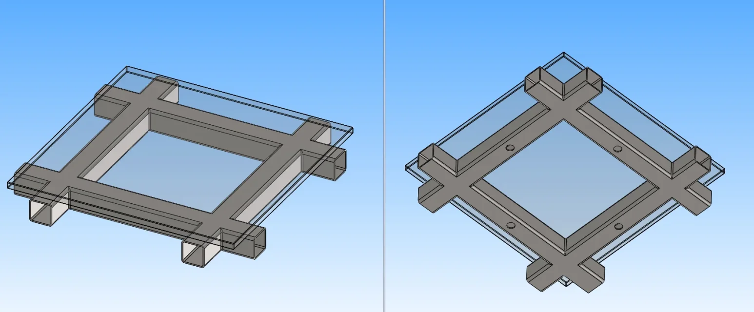
I would like to ask for advice for a rather simple simulation to model but on which I have some dubbbio as set for static calculation; in practice I have a flat grid formed by tubular steel on which a panel is rested; the panel material is not important, what is important is that on it insists a distributed load (for example 100 kg/mq). the grid is leaning on the feet, also arranged regularly.
what is the correct way to apply the load on the elements that make up the grid?
I thought to cut out a part of the grid to exploit the symmetry and regularity of the frame and convert the remote mass panel.
Has anyone faced such a problem or have any advice?
Thank you all in advance for your help and collaboration!
 
I normally model everything and load forces and constraints. if the structure is too complex as geometry you can symmetry with the symmetric study option.
remember to consider gravity.
with xpress simulation you can't do great things.
 
Thanks for the kind answer.
I may have mis expressed myself, I have not xpress but own simulation, only in the basic (or standard) version for static verifications.
I insert an image for clarity
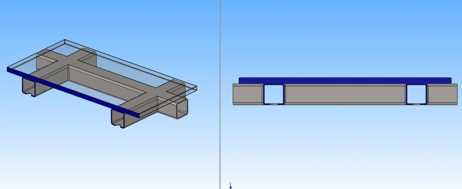
Immagine.webpis a simplified example of a typical problem that, although more complex, can be reduced to it. in practice the glass panel (which could also be of other material) is my "floor" on which it weighs a distributed load, for example 200 kg/mq (from the top down).
the open sections are those where I have continuity with the adjacent grid elements, which I do not consider for simplicity of calculation, and on which I can impose my constraints of symmetry or geometric.
the holes are the seat of the feet and on them I impose the constraints; on this side I can also impose a virtual wall to simulate a support plan.
the question is: what is the most correct way to transmit the grid load of welded profiles without simulating the panel too? I can't simply impose the load on the higher faces because I would change the distribution of stresses in the elements of the grid.
I thought I would introduce a remote mass that replaced the panel for a total weight equal to the load (200 kg/mq multiplied the area) by activating the force of gravity.
any suggestions and/or observation?
 
simply if the glass panel does not cooperate because it is extremely fragile and not bound to the tubular structure except for the support, I would say that you put a force directly on the tubulars equal to the weight of the glass plates and possible contribution of distributed load.
then put the constraints on the holes on the ground.
if the panel contributed, it should be modeled and simulated because it would increase the bending resistance module of the frame.
Hello and thank you for the answer!
As I said in the previous message, the panel can also be concrete or iron, because the aim of the study is to see the effect of the load on the metal structure alone, saving computing resources on a component that I do not have to dimensional or verify.
I thought this: We suppose, for example, to have 1 square meters of surface and that the total load therefore gives 200 kg; if to the effects of the binding reactions (on the holes for understanding where the feet of support are provided) the distribution of the load has no effect, however, changes as the effect on the structural elements.
if at 200 kg distributed I replace an equivalent system of, for example, four 50 kg forces the cutting diagrams and the moment along the sections definitely change (even as they are applied: at the center of the sides of the grid or on the vertices).
from here the need to be able to simulate the load as effectively applied but saving time on the calculation but with results in accordance with how these are obtained!
What do you think/think? any advice?

Hello and thank you again!
 
simply remove the panel and put on the top surface of the tubes your strength formed by the weight panel more distributed. nothing changes on the structure.
I repeat: if the panel is solid to the tubes with screws or welds, then it changes.
 
simply remove the panel and put on the top surface of the tubes your strength formed by the weight panel more distributed. nothing changes on the structure.
I repeat: if the panel is solid to the tubes with screws or welds, then it changes.
hello and thanks again for the answer!:biggrin:
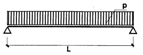
By refusing some science of construction I have made this reasoning that I believe is what you have subtent too: in fact, given also the symmetricity of geometry, if they dissect the grid on one of the two orthogonal planes of symmetry, I have the equivalent of a "just supported beam" where the beam is the section of the panel and the two simple constraints are the sections of the tubular.
Appunti01.webp Appunti02.webpif I solved this "just supported beam" the reactions would be equal p*l/2 (p is the linear load and the length of the beam). therefore on the sections of the pipes I do not have the flender contribution; as this is true for each section and wanting to ignore the panel, considered infinitely rigid, it is equivalent to apply the load directly on the upper faces of the frame.
vice versa I should have taken into account the contribution of the flender moment or calculating it apart or taking into account the fact that the panel is not infinitely rigid and including it in the calculation.
Are these considerations more or less to be done?
anyway, thank you very much for the availability and support!:finger:
 

Forum statistics

Threads
44,997
Messages
339,767
Members
4
Latest member
ibt

Members online

No members online now.
Back
Top