Emc2
Guest
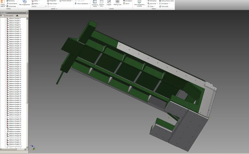
mistakenly thinking that software development and hypermegapotent pc (hp z400 32 gb ram disk ssd 500gb sceda nvidia picture) allowed to carry out the simulated construction of a welded carpentry following the technological process of construction in the model that I would have realized I well thought of performing the procedure using the welded axieme of inventor rel.14.
instead of indicating welds only in the table I followed the following workflow.
I designed the plates to cut to the plasma and created subaxis for the coupling to make the various pieces
I generated the main axieme by going to insert all the welded parts avoiding holes and subsequent processing (some holes I made them to verify then the matching of some plates I would fix later but then I suppressed them).
I converted the welded assembling together .argh!
I have created all the bevels for filling welds (making them with the same sides because if not then they are messed up to create us on the angle or filling welding )
and after reasoning that we are in the 2014 superpower computer I made 140 welding cords on the piece indicating the material
and trying to do them as they would actually be used for later processing.
and become very heavy and unmanageable. insertion of a platelet to put 3 constraints employed almost 10 minutes.
Moreover in many cases if you change a bond the solderings related to the part give error slowing the system ulteriolly.
I wonder how they keep putting such a lock in the package knowing it's unusable.
and I ask how should I perform the workflow to tide the assemblies with the welding bevels to give to the carpenters and the axis with the work to give in the workshop where the welding bevels are no longer visible because covered by the cords and subsequently reworked, are 4 sides of machine cut to the plasma and about 50 connecting plates all beveled for welding.
I think it's mooolto macchinosa.
greetings
roberto

