• This forum is the machine-generated translation of www.cad3d.it/forum1 - the Italian design community. Several terms are not translated correctly.

seven transferable contact

  • Thread starter Thread starter gtsolid
  • Start date Start date

gtsolid

Guest
Bye to all,
I'm modeling a complex structure, where the most yielding component, in my view, is the recirculation skates.
I can simulate their yield through a elastic support And I know the results are approaching reality.
All this works until I have a support on the edge of the model.
If instead you want to recreate something like that between skates within the same, how can I simulate them?
Could I impose a material with a lower elastic module on skates, or do you have better suggestions?
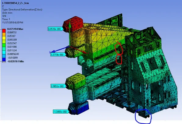
It explains better, you are miserable. Maybe some photos wouldn't hurt.

greetings

sent by my sm-n950f using tapatalk
 
here:1543439000342.webpthe pads in blue I modeled them through elastic contacts. I don't know what fish to take. I tried to put a spring between the components (connection, insert spring).
But I don't understand how the program is thinking by putting the spring, or if it's my case.
 
here:View attachment 51717the pads in blue I modeled them through elastic contacts. I don't know what fish to take. I tried to put a spring between the components (connection, insert spring).
But I don't understand how the program is thinking by putting the spring, or if it's my case.
then it is important to understand whether the yield is due to a game between the elements or the material in contact. in case it is due to the game between the elements the best solution is the use of bushing elements with adequate stiffness. you can also set up a deformation rigidity law as you like, but consider that high rigidities make the model unstable.

sent by my sm-n950f using tapatalk
 
from what I understood the pad+guida system lies on the 600n/micron as rigidity in a translational sense, and practically follows a law similar to that of the "bonded" material in the case of angular stiffness.
I think the guides are preloaded, so the solution could be to weaken the pads with a softer material until I recalculate the experimental results I have.

in case it didn't go well, how does the law impose rigidity-deformation in the wb? would be a custom hooke law f=kx?
in theory assigning the exact materials, if you say it is "as bonded" you should have reliable results. As for the rigidity of the bushing elements is as you say, it is a law of the type f=kx and inserting tabular values do it as you want. bushing elements have 3 translational and 3 rotational stiffnesses.


sent by my sm-n950f using tapatalk
 

Forum statistics

Threads
44,997
Messages
339,767
Members
4
Latest member
ibt

Members online

No members online now.
Back
Top