• This forum is the machine-generated translation of www.cad3d.it/forum1 - the Italian design community. Several terms are not translated correctly.

Dromoaor

Guest
Hello everyone,
I have a problem with construction techniques and I thought I'd put it in this section of the forum.
I have a pipe diameter 500 mm sp 5mm long 1000 mm steel framed at the ends and subject to force in half-work.
to give more inertia to the section of the pipe, not being able to increase the diameter of the same or the thickness, I was thinking to add it inside the reinforced concrete.
the sectional inertias of the two materials are added because they do not depend on the density, but how do I manage the fact that a material has an elastic module of 210 gpa and another 30 gpa?
I immediately thought about the congruence of the two deformations but I cannot understand how to compose the rigidities of the two materials working in parallel.
It would be better for me to add vertical steel ribs welded inside the tube.
Moreover it is quite difficult to establish a priori as you will behave a "trave" so tough.
in mechanical design we have already discussed a tube like yours....and the only thing is homogeneous material and make a fem.
 
hello mechanicalmg thanks for the answer, but before setting long, complex analyses with different materials, with contact patterns between different non-banal materials, I would like to do a theoretical analysis of what I should expect from the finished elements.
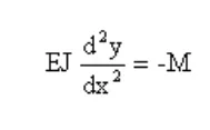
In theory with the elastic line I find the arrow of the beam, but I do not know how to analytically compose the 2 elastic modules and the 2 inertias, in a single formula that allows me to have a total deformity.
I think he intended to tell you to avoid the solution of the concrete, but simply to weld inside the tube a properly sized plate put of knife. Maybe 2 to 180°... so for the fem it becomes easier. . .
 
exactly, as a good mechanic I do not dream of making a structure with concrete inside that traction crumbles.
in my image there is a round tube with a welded iron + inside. increases inertia to bending and becomes all more rigid.
 
I think so too, but I wonder if this solution is not common practice in construction. I have seen several pipes filled with concrete, but only to make foundations (so put upright and stressed mainly by compression). If I have understood, dromoaor the tube has orizzantale, and, with the central load, it subdues it to bending. Maybe that edible strutturist passing through here can give us some notion.
 
Thank you for the answers, but we went out of question.
I put the question in the building/civil design group to ask for a possible theoretical solution of how to compose the matrix of rigidity and not a change of solution.
exact wert, I would like to ask the question to a building strutturist.
I calculated the vacuum tube of steel and the precompressed inner concrete carrot in a completely separate way.
in the generic formula of the elastic line I do not know what to insert in and and j.
I don't know exactly if and of the two materials you sum or not and what to insert by j.Formula linea elastica.pngWhen, for example, I saw how they calculate armor in concrete, the building struts use the homogenized section between armor and concrete to calculate their total inertia. I'd like to see how this beam would fit.
 
I would say that the standard you need to consult is Eurocode 4 and 2 as well as technical standards ntc 2018.
by doing a google research I would say that there are many well-explained dispensers in this regard.

I'll get you a good pair.

However, despite you do not want to change the technical solution, for a 500mm long 1000mm iron tube it remains only the insertion of a couple of plates or a well-tended and welded ipe with welding nails.... especially if you have to sign and then assume civil and criminal liability.

However your pipe will be beg because it is thin and not because the span is long and you cannot use any of the usual formulations in use for beams.

read the debate that we did time ago.
 

Attachments

If I am asked to analyze a technical solution, I cannot change the possible technical solution because I cannot analyze it.
If I can't analyze it, I try to figure out how it should be analyzed.
thanks the same for the help.
 
fundamental concepts are homogeneization, viscosity and partialization.
the quantities and*i are not added because they do not consider, precisely the phenomena of viscosity and partialization. the problem is not linear even in exercise, not only in last conditions.
many aspects have been simplified in the calculation of c.a. and mixed sections due to their complexity.
in good substance a section in c.a. Concrete homogenizes by amplifying the steel rods of factor n = es/ec (ec is reduced by viscosity).
Mixed sections prefer to homogenize steel by dividing the portions in cls of factor n = es/ec.
in both cases the concrete does not work at traction and therefore it must determine the reagent section.
in the case considered there is an area section 7775 mm2 and j=2,38e8 mm4.
I want to use the vcaslu program for the reinforced concrete sections and for my convenience I replace the tube with a series of 70 tondini of diameter 11,892mm places on the rims of diameter 495mm. This allows you to calculate the reagent section and tells me that the neutral axis is positioned at 197.2mm from the maximum compression point.
the program provides values for uniform concrete areas. it will then be necessary to divide for 15 to have steel ones:
a = 187919/15 = 12528 mm2
= 4,54e9/15 = 3,03e8 mm4
then the calculation of the arrow should be done considering the fact that the beam is variable section (because the cls is integral between the cracks). Amplifications due to constant load viscosity should be considered, but for such a case it is likely that they are not influential.
in the face of the filling of cls (notable weight increase) we have a modest increase of the moment of inertia (of course considering all the cracked beam) of 27%.
probably by doing the correct analysis of the whole parts you could rise to a 60%.
I'm sorry, but now I don't have time to get into it.
Maybe later I'll write more about it.
 
I recognize that I do not know practically anything about concrete, it behaves like a composite, but with the difference that does not work traction. thanks to the explanation
 
I would form a sort of straw filling the tube of steel rods, anchoring them to the concrete but only at the ends. How do you do with the rocky bridges suspended? I don't know if you can calculate such a structure. We still talk about a length of only 1 meter, so you can also oversize without particular problems.
 
therefore, reading what explained by cls specialists we are to reiterate that "concrete emptiness the tube" we do not go far with mechanical resistance.
Then again I repeat that we need to weld iron plates inside the tube to increase inertia.

a long time ago we made a similar discussion on a sheet coated with a nice thickness of plaster. It is true that they both collaborate as long as the less tractable material does not yield. However, at the security level, he had taken the stucco not to cooperate.
 
Yes of the beautiful cross ribs welded inside the tube, the concrete resists compression not to tensile or bending it seems to me!
 
@ondaExcuse me. My answer didn't mean it wasn't composite materials. I noticed after maybe I was a little disrespectful to you. Yes, reinforced concrete is a composite material with the fundamental property of adherence which is basically always guaranteed.
there is this engrave of the festive (and also of the viscosity understood as a property to continue to deform even to constant effort in time).
@meccanicamg I would like to stress the problem of deformation more than in resistance speech.
In reality the deformed will be a middle way between the section entirely reagent and section completely partialized.
and in reality the arrow will also have a modest growth in time due to the degree of maturation of the material and to when it was put into charge.
voluntarily the resistance can be improved by inserting armor bars.
we say that this solution works better with the pillars than with the beams.
so much for comparison I wanted to insert 8 bars of diameter 14mm (admitted are a little few views the size) and get a strong moment (steel limited to the resistance of pipe and concrete c25/30) of about 375 knm (partial steel coefficient 1,15 for bars and 1,05 for tube and concrete 1.5).
the resistant moment of the tube (plastic moment) divided the partial safety coeff. 1,05 is worth 274 knm. we say that there was a gain of 375/274=1,37 about 37%.
Of course I would have had a greater gain compared to the elastic moment that is worth 213 knm. here I would have had: 375/213=1,76.
If the comparison is made with elastic value then things seem interesting.
 
Hello dromoar, hello to all
I put myself in the discussion because I am a civil engineer.
but my considerations are identical to those of legs that also cited the program gelfi for the actual verification of the section.
There is also a legs that writes on ingforum with which I have already been able to exchange some opinion. an extra reason to say goodbye (also on the move).
I wanted to add some additional consideration.
1) the homogenization coefficient used to homogenize the structures is equal to the ratio of elastic modules m=ef/ec. we assume the value of 15.
2) theoretically it is possible to homogenize the structure by multiplying the steel area by 15 and, therefore, calculate inertia, tensions and deformations.
but you must be absolutely sure that the two materials are intimately connected and there is no flow between the two.
and here is the problem.
while in a section of cls containing cls bars we are sure that there is no sliding between bars and cls, we can not say as well for a pipe filled with cls because, you want for the withdrawal of cls, you want for the different states of effort, the absolute adherence is not guaranteed.
then all theoretical speeches jump and skip fem analysis because you can't reproduce these relative movements.
for these reasons, and in favor of safety, I when design steel pillars make cls filling abstraction and consider only steel.
Hi.
 

Forum statistics

Threads
44,997
Messages
339,767
Members
4
Latest member
ibt

Members online

No members online now.
Back
Top