• This forum is the machine-generated translation of www.cad3d.it/forum1 - the Italian design community. Several terms are not translated correctly.

conversion file tekla

  • Thread starter Thread starter il_Batto
  • Start date Start date

il_Batto

Guest
Good morning, everyone!
I am a feder and I am a designer who uses inventor as 3d.

I don't know if I'm in the right section for my request.

I'm designing a high-light cocke treatment vacuum system. I take care of the whole part of pipes (modeling and construction drawings) and planting, following the layout and coordination of the design and realization of drawings for workshop.

all the 3d model of the plant has been realized with inventor and also the other phases are organized with my employees using autodesk products. Unfortunately with the workload that we have the part of structural carpentry we had to delegate it to external office. they work in tekla.

complete modeling of the structures, they sent me a file in dwg. the received file consisted of a set of mesh that at the time of exporting it to me (in step - for other file steps with other studies) I got a file of 1 giga and a half. obviously unmanageable from a normal pc.

do you know if you can export from tekla to a format (possibly dwg or step) and get solids in the model?

thank you for the help and I apologize if I have wrong area to post the request.
 
the easiest thing is to ask who made the drawings to provide them in a more or less "classic" interchange format. ..type the dear and old "step" or "igs"....want or nolenti with their small magagne...the "dwg" for the 3d as interchange format is beautiful (with all respect) like the merkel

I don't know how to use it and anything else I can't recommend. . .
 
Good morning, everyone!
I raise the need to help me find a solution.

from the suggestion of @ale47p I have not been able to have results, as the engineer who works for us is not collaborative from this point of view and I cannot in any way talk to his technician who uses it.

If there is in this section a tekla user can help me?
news regarding the initial post is that they provided me a revit license, but seen the period, I have not yet gone to do the course.
Could it be a useful tool for conversion?

I really need to have the lightest facilities possible as I can't handle the full model in any way.

Thank you!
 
Can you attach a file?
I do not use inventor, but solidworks; long ago I found myself using tekla derivative files and had converted a dwg with fairly acceptable results for my needs.
but not guaranteeing results , I can make a test
 
Good morning.
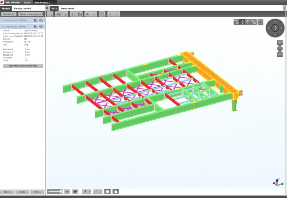
I attach a video capture of the platform obtained by tekla bim sight
(free viewer of tekla)
You will tell me: "and I what can I do with bim sight?
practically nothing,
you can at most see how it was structured in tekla.. .
Good luck:)Cattura Tekla BIM Sight.webp
 
thanks for both info.

I did some evidence with the client and exported his model to step.
the problem is that the parts of the model are surfaces and not solid, and each surface consists of triangles forming a mesh.

on a complete structure create infinite triangles to compose the surfaces of each plate or beam.

generated files become unmanageable
I fear that there is little to do, tekla is a Leviathan who devours only putrelles and distinct expelles of cutting large models like a football stadium. by force of things manages only the primitives of the edges and not the whole solids. I don't know inventor, but by consulting the tekla model with bimsight, can you ask him to do some sections where you have to pass the pipes and stick the dwg on "sketch 2d?!? "
 
to make my verifications use also naviswork that import any file type.
only that naviswork is just a program, which matters a thousand different formats, where you can make still images for comments and share notes and other, but you can't impaginate anything.

the problem comes to me when I have to imply the complete model of the plant
you also shipwork is only a viewer. Anyway I searched in my archive carpenter step files received by tekla users, they for there I did not remember, but I saw that they are solid 3d! Maybe the parapet tubes are octagonal, but for the beams there is no problem.
I think there are several add-ons for tekla more or less expensive or free that make translation work in step.
in my case the plugin was called: open cascade step translator,
and perhaps also depends on the more or less high definition settings attributed to the specific project.
 
I tried to export to iges, which you find attached, and then import it into solidworks from which I then exported it to various formats that I attach to you. the pc with which I did the job is not performing so I could not do a repair/union of the surfaces that were quite numerous.
 

Attachments

@massivonweizen Thanks for the conversions and I have to say that I'm the one who does it to my case.

only thing I'm not clear about the steps you got solids with.
I try to sum up the steps:
1- Open my dwg with autocad
2- exported from ac to iges
3- Imported into solidworks
4-exported in attached formats

correct?
because I tried to do so but I always get a model of surfaces and not solid like yours.
Did you make any special export tricks?
 
I didn't do anything in autocad export.
as soon as the import and subsequent export is concerned, I imagine it depends on the program; with inventor I don't know what parameters you need to set.
 
link to download the converted file to inventor 2019:open the sent dwg.
exported to iges.
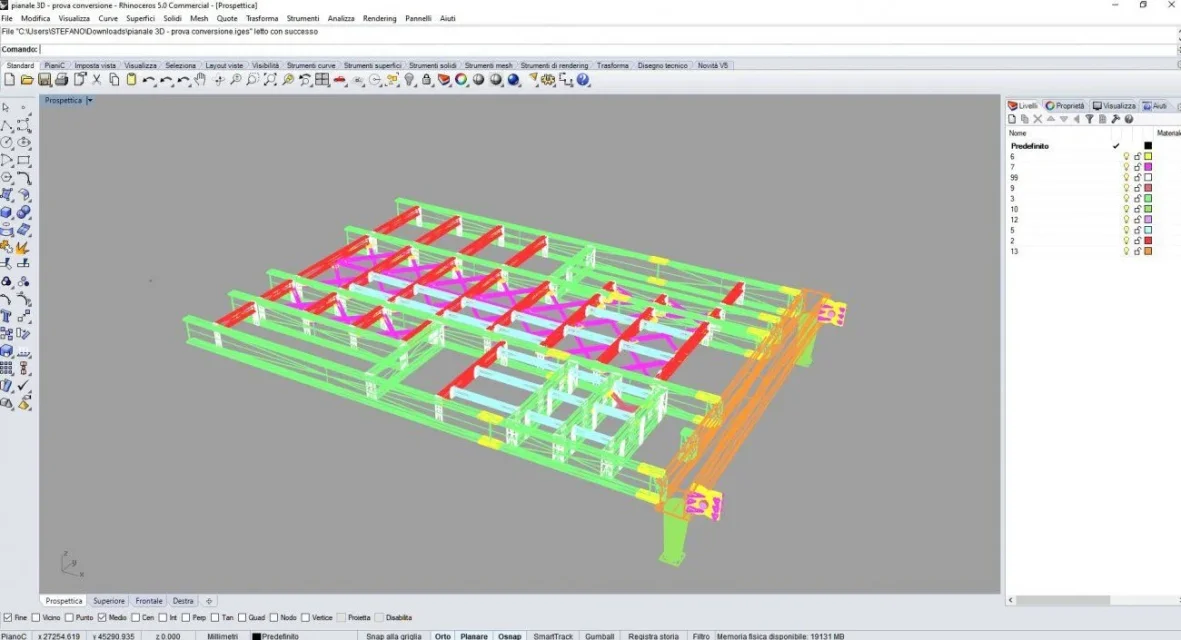
open with rhino and made some small adjustment, on average it was already in place, except for some open surface.
saved and opened the .3dm file in inventor ( 100% solid )
without the pass on rhino, but opening the igs file with inventor, the situation was pretty nasty.
If you need, I'm available.
 
Thank you. @ Stefanobruno!
talking to my architect friend also suggested that I pass conversions in rhino, as it grinds models differently from the usual modelers.

I had also made some evidence as suggested by @massivonweizen but obviously solidworks converts differently.

Today I try to download a trial version of rhino and try to see how it behaves.
also because the frame I shared is only a small part of all the structures I have in the project.

I'll wait as soon as I can do conversion tests

thanks for the support!
 
If you need it, to maximize the use of rhino, I can describe the minimum steps to succeed in conversion.
the 1000 heuri of rhino, spent once and then never again, solve many similar cases, with 4 commands 4.
 
If you need it, to maximize the use of rhino, I can describe the minimum steps to succeed in conversion.
the 1000 heuri of rhino, spent once and then never again, solve many similar cases, with 4 commands 4.
If you can explain the commands you would do me a big favor....
Thank you!
 
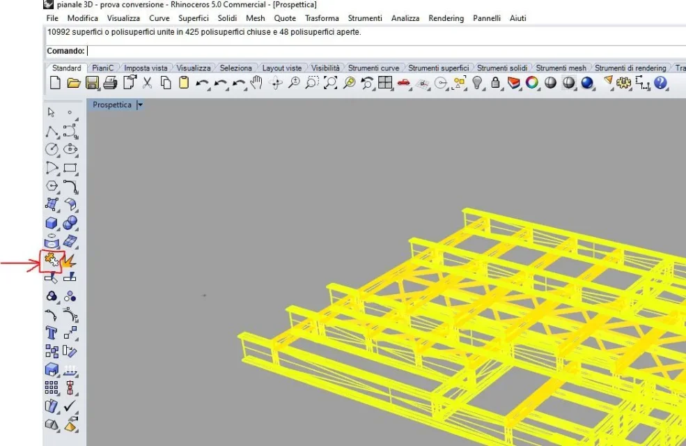
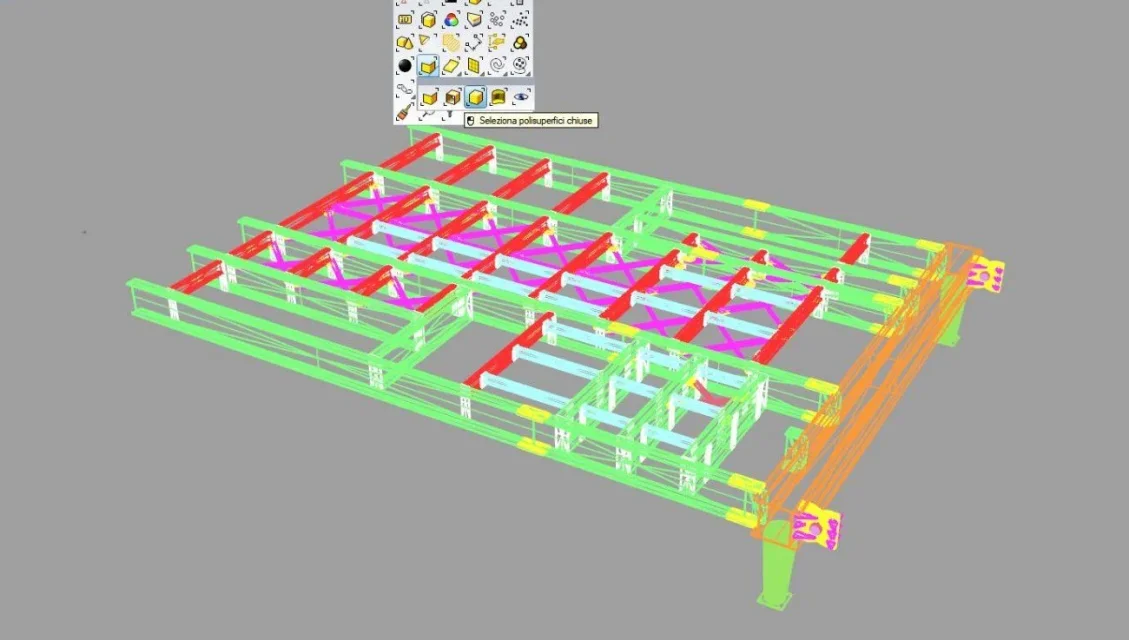
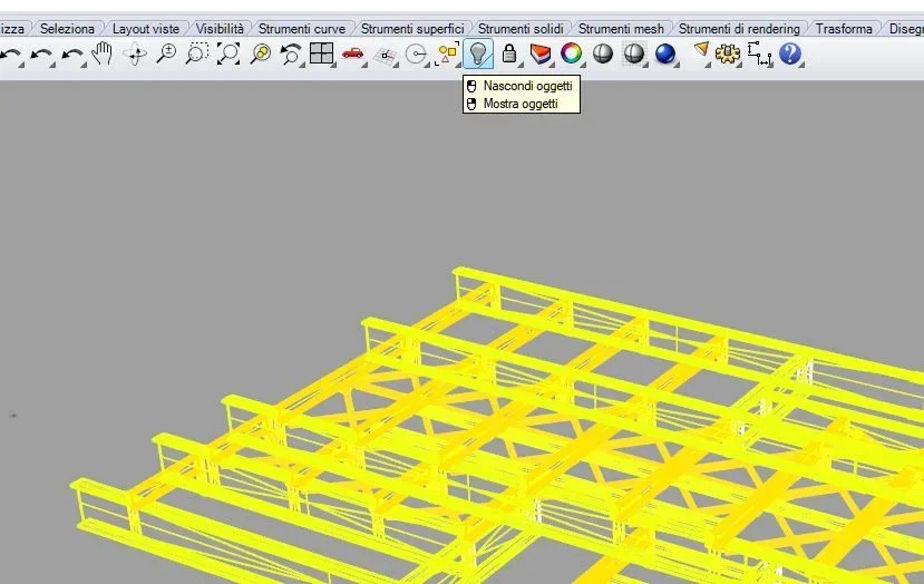
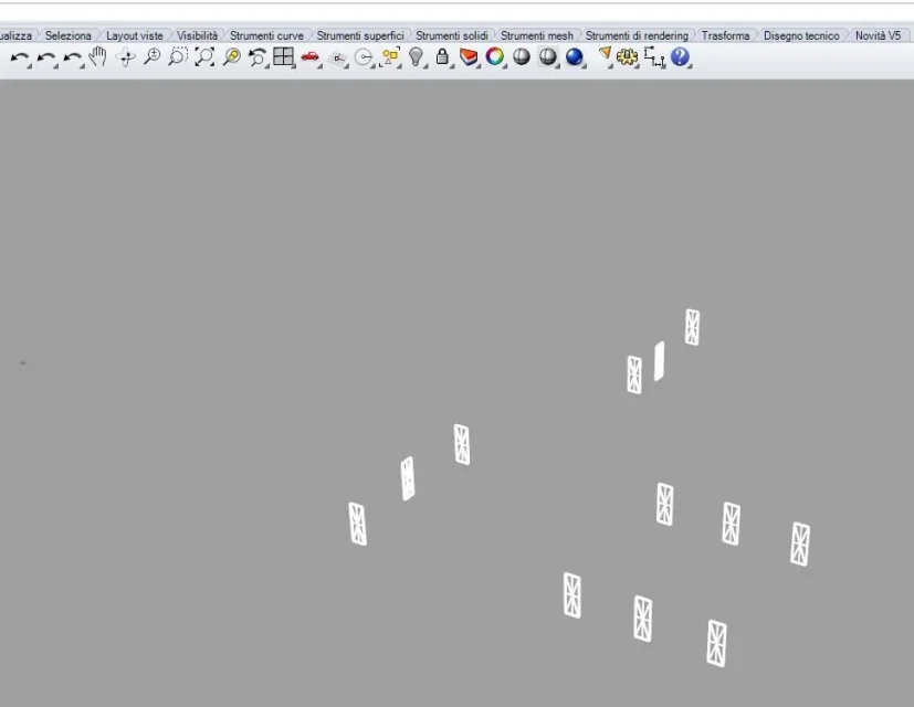
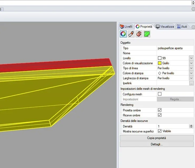
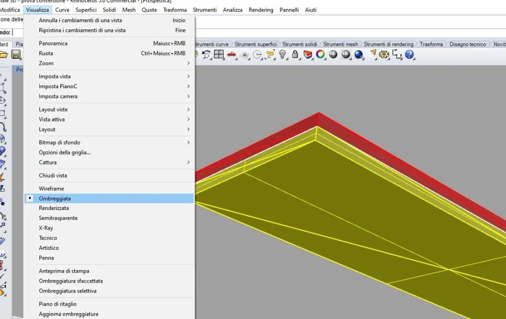
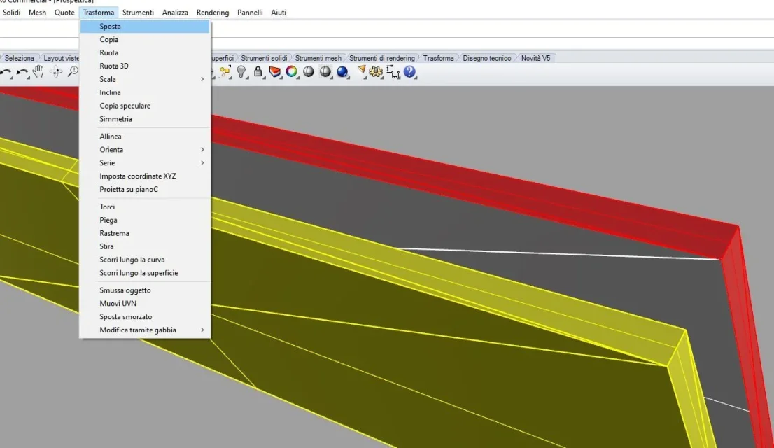
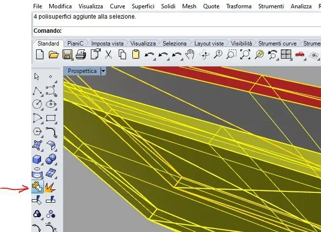
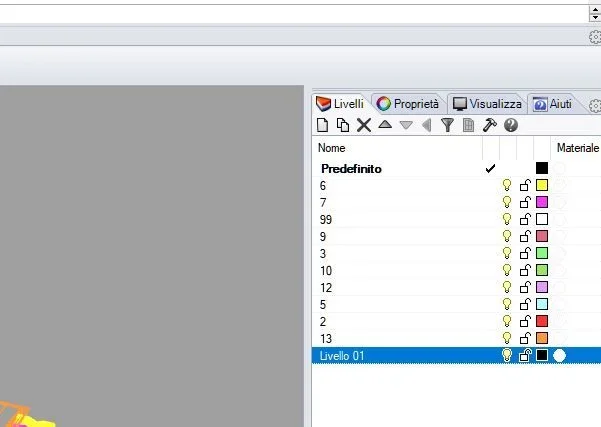
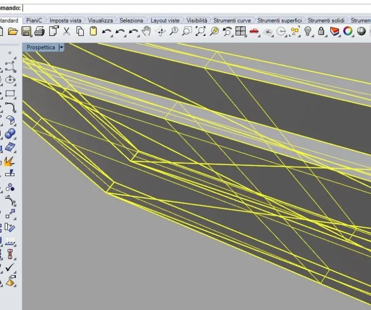
open igs file and see thisApertura file igs.webpSelect everything with a window and join the surfaces with this buttonPulsante unisci.webpselect closed polysuperficiesSelezione polisup chiuse.webphide objectsNascondi oggetti.webpremains this, which are open surfacesSuperfici aperte.webpto clarify, I changed color to the surfaces and shaded the same.Cambia colore.webpVista ombreggiata.webpbetween the red and yellow polysurfaces, there are two surfaces that make up the 6th side of the two plates, for comfort shifted the red polysurface and one of the two surfaces enough to facilitate the next operation.Sposta superfici.webpselect, with intersection window, objects and join them.Unisci superfici.webpKeep it up.
 

Attachments

  • Crea nuovo livello.webp
    Crea nuovo livello.webp
    13.6 KB · Views: 4
Here I am with the closed surfacesSuperfici unite.webpat this point you bring back the surfaces you had moved, which are now united, to their place.
All this I did, for simplicity, only on two polysuperfici.
it is possible to do it simultaneously on all, even if it requires a little attention and the use of the "maiusc" button to add the entities and "ctrl" to remove them.
the pieces to be treated are few, you can also proceed to passlets.
make everything visible, with the bulb you used to hide the closed polysurfaces.
save (in .3dm ) and open the file in inventor.
sweaty, let me know if you did.
 

Forum statistics

Threads
44,997
Messages
339,767
Members
4
Latest member
ibt

Members online

No members online now.
Back
Top