• This forum is the machine-generated translation of www.cad3d.it/forum1 - the Italian design community. Several terms are not translated correctly.

dimensioning toothed wheels to helical teeth

  • Thread starter Thread starter Raffaele98
  • Start date Start date
by reasoning we can say that:
- if all gears are cemented and hardened, they have the maximum mechanical characteristics and by force of things we will have smaller wheels and pinions than only hardened materials or only reclaimed. So having 2 stages with the same sigmah is fine.
- other thing is definitely that the number of pinion teeth must be as little as possible to and have the module just verified to have a minimum volume
- clearly if increasing the module for hertz needs will decrease the band width but equal teeth increases the volume of the outer diameter
- if increase the band to improve hertz does not increase the diameter but increase the cylinder height and then increase the volume

In fact, complete verification should be made in accordance with and tabulate all the options....only so is the minimum volume, that is one absolute couple that meets the criterion. I believe how you are doing now you are looking among the minimum possible volumes but not in the absolute minimum.
well all in all better than to shoot at case m1=10 and m2=20.... that then comes out a huge reducer like a house.
 
try to make an example with this method:

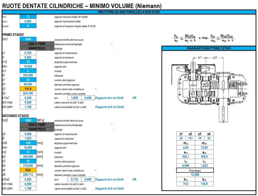
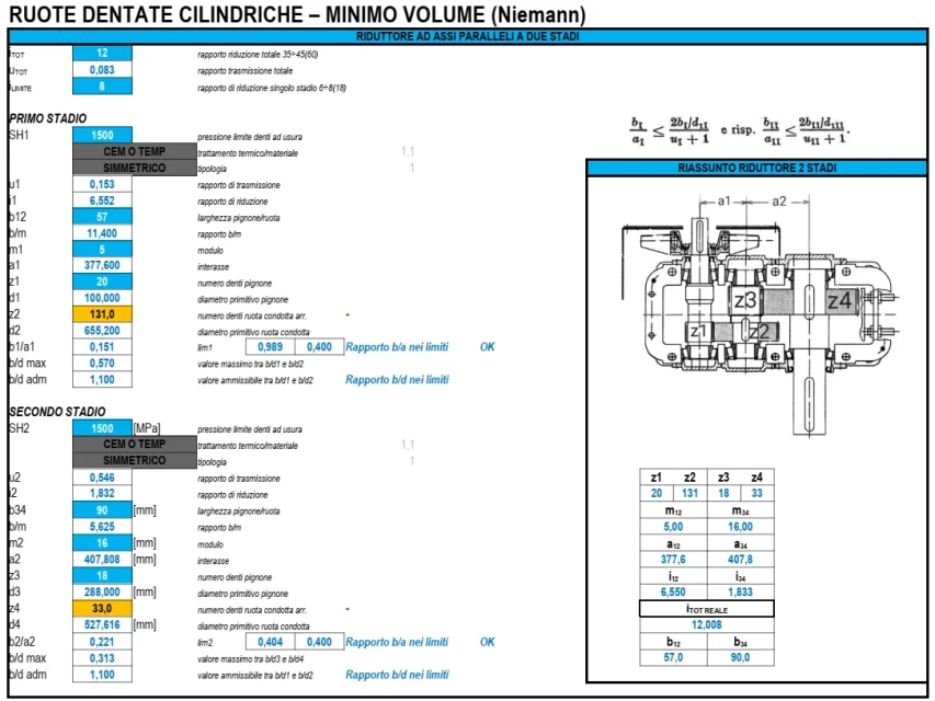
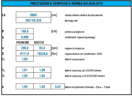
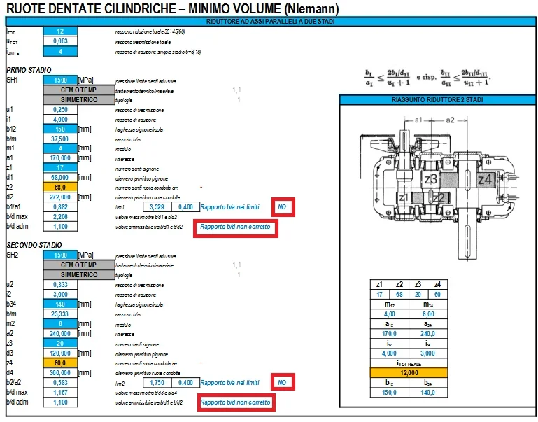
- We calculate a 2-stage reducer with i=12 with ingesso 160kw-1000rpm - 5000hr service with standard iso 6336:2019 - cementation steel sh1500mpa. after a few attempts we come to define the modules and the bands.
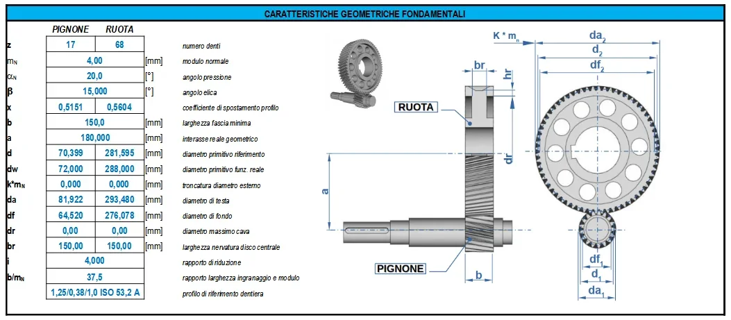
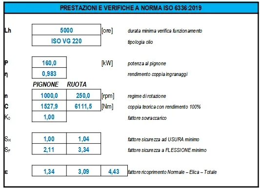
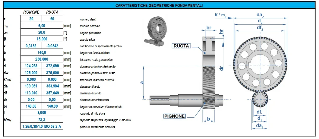
1639054668590.pngWe quickly calculate the volume, indeed the weight (which is the same thing) using the primitive diameter and the band width ....for a total of 289.4kg1639055007879.png- now we see to carry out with the same materials something different on the modules/widths1639055637176.pngwe calculate again the weight that is a total 368.6kg who is a 27% of difference1639055503947.pnganalyzing the safety factors on bending and wear on the various gears, we have that all gears have the wear factor (that of hertz) just equal to 1 in order to resist the operating hours for wear. the bending factors, however, turn out above 1.5 for the first reducer and above 2.6 for the second reducer. this we expected because increasing the module, increases the size of the tooth. the second reducer also has a little imbalance on the second stage due to too much load capacity compared to the first stage. Moreover from one stage to another, it hardly should double the module but should be gradually increased slowly because however a double module has a remarkable load capacity even if I just made a stage with ratio 6.
summarizing the question, the formula works (that of niemann for the minimum volume) only if you do the checks starting from the smaller module and going up with the iterations as long as it is verified. Surely with hand calculation it takes a lot to get to convergence by doing the checks in accordance. for this, at least the use of excel to have the checks I would say that it is the best tool to use.
 
Thank you very much, in the evening I will deepen the complete formula of hertz, and if I have any doubt I will write here.
 
a last question the checks placed on the bonfiglioli manual and on the practical manual of henriot gears are okay?
 
a last question the checks placed on the bonfiglioli manual and on the practical manual of henriot gears are okay?
the verifications of the manual of the driver of bonfiglioli are the iso6336 of 2008, however exceeded since the last is of 2019 but good enough for a calculation still current. So I suggest you look at them.
 
the verifications of the manual of the driver of bonfiglioli are the iso6336 of 2008, however exceeded since the last is of 2019 but good enough for a calculation still current. So I suggest you look at them.
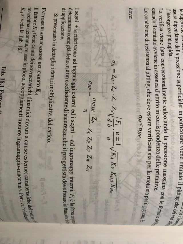
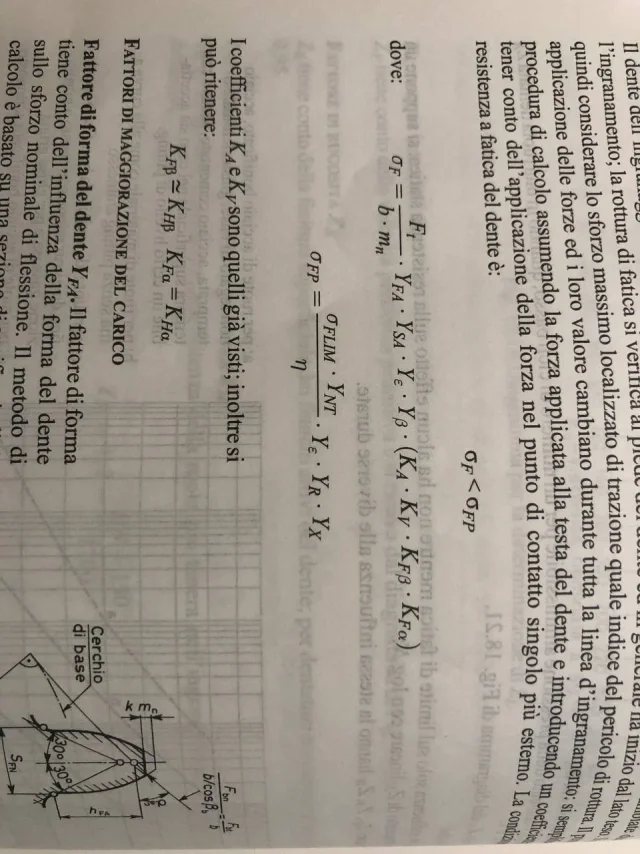
are these formulas correct?photo1639060482 (1).webpphoto1639060482.webp
 
try to make an example with this method:

- We calculate a 2-stage reducer with i=12 with ingesso 160kw-1000rpm - 5000hr service with standard iso 6336:2019 - cementation steel sh1500mpa. after a few attempts we come to define the modules and the bands.
View attachment 64032We quickly calculate the volume, indeed the weight (which is the same thing) using the primitive diameter and the band width ....for a total of 289.4kgView attachment 64033- now we see to carry out with the same materials something different on the modules/widthsView attachment 64035we calculate again the weight that is a total 368.6kg who is a 27% of differenceView attachment 64034analyzing the safety factors on bending and wear on the various gears, we have that all gears have the wear factor (that of hertz) just equal to 1 in order to resist the operating hours for wear. the bending factors, however, turn out above 1.5 for the first reducer and above 2.6 for the second reducer. this we expected because increasing the module, increases the size of the tooth. the second reducer also has a little imbalance on the second stage due to too much load capacity compared to the first stage. Moreover from one stage to another, it hardly should double the module but should be gradually increased slowly because however a double module has a remarkable load capacity even if I just made a stage with ratio 6.
summarizing the question, the formula works (that of niemann for the minimum volume) only if you do the checks starting from the smaller module and going up with the iterations as long as it is verified. Surely with hand calculation it takes a lot to get to convergence by doing the checks in accordance. for this, at least the use of excel to have the checks I would say that it is the best tool to use.
hello good morning, it is not clear to me one thing, that is by applying the formula reported on the niemann for the minimum volume, considering i=12, I exit an i1=4,19 and not 6,55
 
hello good morning, it is not clear to me one thing, that is by applying the formula reported on the niemann for the minimum volume, considering i=12, I exit an i1=4,19 and not 6,55
I think you used two different values of sh.
niemann says for the two-stage reducer:1639237139707.webpthen inserting the numbers I used I get:1639237172949.webpso I get the reduction ratio as reverse of the transmission ratio:1639237198828.webpWhat's wrong with you?
 
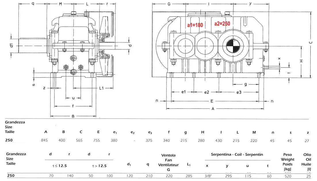
just to deepen, the reducer we are planning, according to a well-known manufacturer of old-fashioned gearboxes, should be size 2 stages 250, that is this here.1639239804724.pngthis is realized to make total effective ratio i=12.247 and is given for 181kw-1000rpm.
already at the first analysis, we see that the commercial reducer is smaller than our first version reducer with a1=302mm and a2=306mm. Here we have 178mm less on the total quake.

going to calculate what can be in it, let's see immediately that you can't think of making a relationship around i=6.5 because the verification of wear with hertz is usually not verified for 5000 hours. so we can think that if you can do i=12 in a total interasse smaller than that of the "minimum volume" means that there are no optimization parameters.

Let's see what I would have done without using minimum volume indicated by niemann.

we limit the real feasibility of the first stage with i=4 as normally at the industrial level we do with the multi stage. niemann also says to limit it, even if it does not explicitly say so and above all remains vague:1639240739881.pngsvilupiam
first stage1639240336461.png1639240361774.pngsecond stage1639240505582.png1639240524512.pngweight of wheels and pinions, without pieces of tree/cuscinettery and other, so as if we were making the comparative volume=weight.... we get1639240925580.png
p=209.6kg..... the minimum of volume and weight limits compared to all models previously analyzed of reducer.

I personally have never adopted the principle of minimum volume calculated as indicated by niemann but I use my method which consists in subdividing for each stage the same value of reduction ratio.

each stage will have a reduction ratio given by the desired total ratio elevated to a divided number of the reducing stages (to make i=12 with 2 stages i1=i2=3.464).
[math]i_{stadio}=i_{tot}^{(1/n_{stadi})}[/math]Unfortunately I did not find the method of the minimum volume explained on other texts. I know kisssoft uses it in the criteria of choice of gears but as I remember it had never been the best system to select gears.

clearly analyzing the values in the calculation of the minimum volume do not agree with the parameters....even the reducer would have been built like this.
1639241721523.webp
 
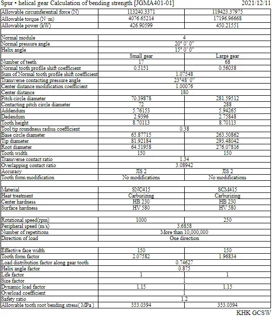
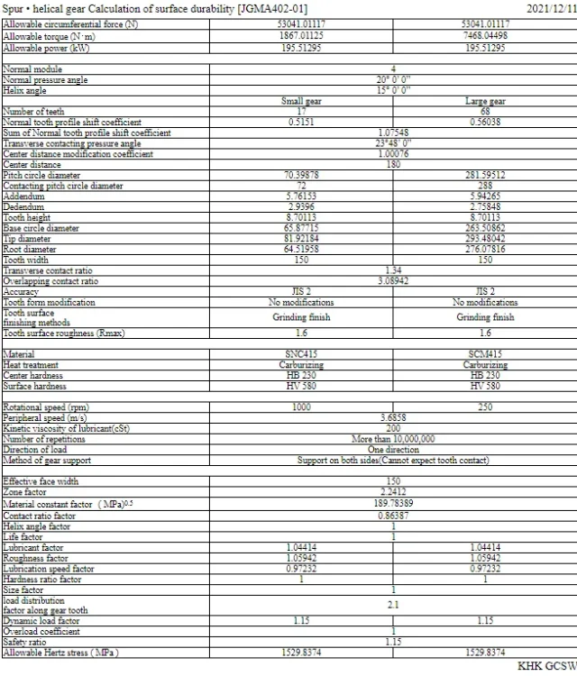
the norm you are using from the driver's manual - bonfiglioli, is quite comparable with the jgma402-01. for this reason, you may use a further comparison of the khk gear site, where there is free, after registration, the online calculator for gears.

it is clearly comparable with the iso 6336:2008 but not much with the iso 6336:1019 because different coefficients for the operational robustness of the tooth and on the various gear trains there are those that have earned 20% and others have lost it as transmission capacity.

For example, always our first stage of the previous post, has the following report:
fs=426/160=2.61639245510744.webp
bh=195/160=1.21639245474022.webptherefore, all in all, provides us with agreed data with previous calculations.
 
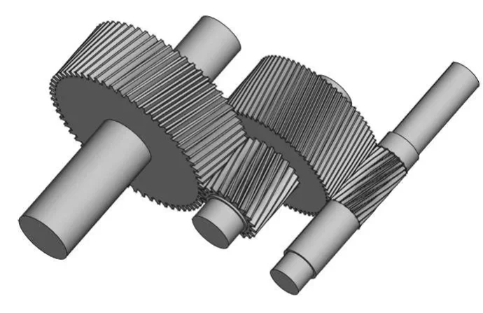
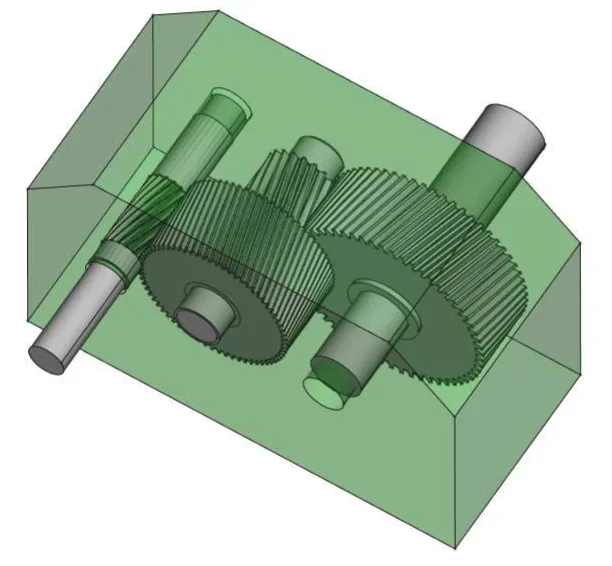
further, developed on the fly with freecad 0.19 with workbench fcgear, part design and workbench together with 2plus.... a work of about a quarter of an hour.. .
1639250828634.pngthe input shaft obtained from full and carved the elica of the gear. Like this tree down here.1639253121958.webppinion second stage obtained from full integral with pinion.
the two wheels of the two states calettate with tongue on the respective trees.
the external volume is that of the above mentioned trade reduttor and actually we are in it well, so it means that the internal subdivision logic of the reduction ratio with the first stage i=4 and the second stage i=3 worked correctly.
1639251004789.pngbeing that this reducer to catalog has been definitely designed with old regulations, it goes from itself that the gear bands are deducted from, according to always the criterion used at the time, of a 10-20mm so as to have a little more useful space as it would seem to be there in catalog.
 
Last edited:
further, developed on the fly with freecad 0.19 with workbench fcgear, part design and workbench together with 2plus.... a work of about a quarter of an hour.. .
View attachment 64057the input shaft obtained from full and carved the elica of the gear. Like this tree down here.View attachment 64059pinion second stage obtained from full integral with pinion.
the two wheels of the two states calettate with tongue on the respective trees.
the external volume is that of the above mentioned trade reduttor and actually we are in it well, so it means that the internal subdivision logic of the reduction ratio with the first stage i=4 and the second stage i=3 worked correctly.
View attachment 64058being that this reducer to catalog has been definitely designed with old regulations, it goes from itself that the gear bands are deducted from, according to always the criterion used at the time, of a 10-20mm so as to have a little more useful space as it would seem to be there in catalog.
so should you make tree and wheels of the same material?
 
Good morning, I had done u1=0.8*(12)^2/3, since on niemann it was written: View attachment 64069
actually with these indications i and u with a mess.
in the manual sometimes calls the like u and vice versa but I think you're right. We don't have to do as I did but as you did. It should be so because it should not come a high but low relationship.
it would be interesting to deepen and clarify the doubt.
at some point he says: total transmission ratio i....place equal to u.............
It means he takes the and writes it as u... but if u is a reduction report... but then he calls under transmission i.
So what?
I've always hated a mess.
 
at some point he says: total transmission ratio i....place equal to u.............
It means he takes the and writes it as u... but if u is a reduction report... but then he calls under transmission i.
So what?
I've always hated a mess.
I used them, but I'm not convinced
 

Forum statistics

Threads
44,997
Messages
339,767
Members
4
Latest member
ibt

Members online

No members online now.
Back
Top