• This forum is the machine-generated translation of www.cad3d.it/forum1 - the Italian design community. Several terms are not translated correctly.

injection moulding component with holes

I press that I couldn't open the file that you attached, so I will only base myself on the images that you have attached and victorious.
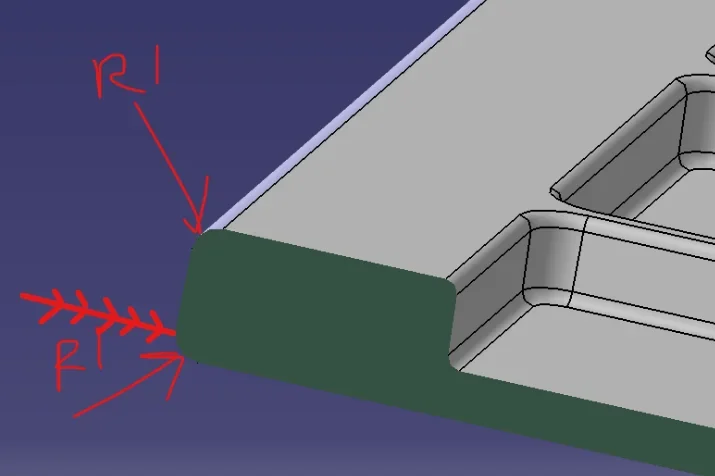
in the fourth image placed by victorious (with the rays indicated by hand): if the opening of the mold takes place on the lower surface (opposed to where the trays are), you cannot put a radius. You'd create a subsquadro.
Moreover the wall under the trays has a thickness while the edge has an excessive.
to avoid it, in my opinion, creates the solid first, the sforms, downloads the trays and the sforms and after you create a "guscio" removing the lower surface (I don't know the name of the command). This makes you a solid with uniform thickness at all points. and if you first add the radiations on the edges, the program adds the correct internal ones with the specified thickness.
only after adding the tabs.
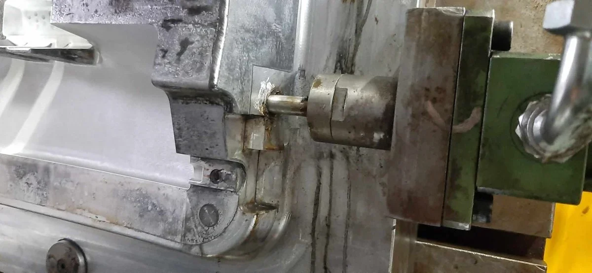
about the tabs, in the second and third image you posted there is a small pocket between the tab and the edge: if possible I would tie the aletta so as to remove it. the mold would be easier with less processing.
about the reforms: you can choose different reference plans. if you take the closing mold you will have to indicate tenths of degree, to contain the moving of the surfaces. if you take the one from which the protrusion of the aletta can indicate degrees ( easier to manage) and the shift will be minimal.
the rule, with the sforms, is that you have to see all the surfaces both on one side and on the other.
If it doesn't happen, you have to check if there's a subframe or if you've forgotten a surface.
in any case for important details, such as these fins, you have to add ray everywhere.
At least those of the attachment must be "important".
 
in the fourth image placed by victorious (with the rays indicated by hand): if the opening of the mold takes place on the lower surface (opposed to where the trays are), you cannot put a radius. You would create a subsquadre
there is no subsquadra if the mold cut is done at the end of the radius .
avoids the live edge that aesthetically is always ugly to see and touch.
1680558176532.png
 
there is no subsquadra if the mold cut is done at the end of the radius .
avoids the live edge that aesthetically is always ugly to see and touch.
View attachment 68026
@vittori It's the solution I'd adopt, too. @et3d , no further information: If there is a part in sight, for example, because in that case I would tend to make it in part fixed, otherwise you see the signs of the extractors. if there are other mating pieces that could interfere if there are particular sforms. The sform also depends on the type of finish you want to get if you do an embossing, for example, you will have to use generous sforms. . .
 
Good morning, guys.
thank you very much for the answers, after seeing the victorious document and your advice I understood better how to fix the piece. Today I try to give it a system so as to give it to the molder as correct as possible.

:
 
hi et3d according to me you are becoming mad to avoid 2 pistons from 200 euros to make holes and you are neglecting other, I recommend you to talk to the printer that will go to print the particular, he will know to best advise you on how to and why to insert cracks, know to advise you the ideal thickness to have a good filling and know the technical characteristics of the material you want to use evaluating is suitable for your needs. another tip is to identify the exposed surfaces and their finish this influence on the decision of the closing lines, and on the minimum angle of sform.
 
hi et3d according to me you are becoming mad to avoid 2 pistons from 200 euro p
Maybe it's a 6-print mold and 2-pistons become 12
The less movement there are and the better.
for the series... more things are breaking.
 
according to me it is always all relative,
and we do not have sufficient information to evaluate everything. .
It is true that fewer movements are there, the better.
but I, personally, have never loved closing surfaces between matrix and punch, so small, maybe with 1/2° sform. .
if we put on a multi-print mold, those closures last little,
they seize, they are adjusted, they seize again, via limatrice,
At that point, the bava appears, which doesn't make you go to mate the pin of the counterpiece, then you have to remove the bava in a rognose place. .

everyday life. .
exact, simplifying does not necessarily mean removing. just for the lack of information it becomes useless to give opinions on a forum on such a complex topic the easiest thing is to turn to those who have the necessary experience that will ask all the info of the case, by now all the printers offer the service of verification feasibility or coengineering so much it is worth exploiting the service and to save themselves rogne.
 
but I, personally, have never loved closing surfaces between matrix and punch, so small, maybe with 1/2° sform. .
if we put on a multi-print mold, those closures last little,
I have to say the opposite regarding my experience.
certain 0.5° definitely creates problems, but with appropriate sforms it works.
many snap-fits are obtained between punch and matrix without movements.
the movements always give problems, remain backwards for misfortunes due
Also to lubricants deposits and the clean hole is not guaranteed anyway.
We do not have sufficient data to make specific considerations.
I think we can spend days discussing what's best.
You're right victorious.
about the corners of sform, where and if possible, I apply a rule of my "old" mentor. .
el vin bon l'à almanco 10°, mejo se 12.5.. (good wine has at least 10°, better if 12.5.. )
 
You're right victorious.
about the corners of sform, where and if possible, I apply a rule of my "old" mentor. .
el vin bon l'à almanco 10°, mejo se 12.5.. (good wine has at least 10°, better if 12.5.. )
You see we're relatives?
That phrase was a battle horse of my grandfather too.
If a damigiana of wine was broken, she cried .:roflmao::roflmao:
 
hi et3d according to me you are becoming mad to avoid 2 pistons from 200 euros to make holes and you are neglecting other, I recommend you to talk to the printer that will go to print the particular, he will know to best advise you on how to and why to insert cracks, know to advise you the ideal thickness to have a good filling and know the technical characteristics of the material you want to use evaluating is suitable for your needs. another tip is to identify the exposed surfaces and their finish this influence on the decision of the closing lines, and on the minimum angle of sform.
is not so much the cost of pistons in itself but all the components connected to it (slittings, possible guides, etc.) and the processing to be carried out for the above sleds (seeds for sliding, various drilling, etc...).
In addition, as rightly said, if the mold is at multiple cavities, the costs multiply.
other thing the management in the foundry of a mold with movements is increasingly "rognose" compared to an open-hearth, even if it changes between sectors (for example a plastic mold will be increasingly "clean" of a die casting mold, and therefore more convenient to manage).
are 2 side holes do not need slides guide skates (which would serve with shorts controlled by tilted thorns) nothing 4 holes and 2 spacers. in the laboratory I have 150 moulds with 1 or more free or sequential movements combined and not to shun some han more than 30 years and are still beautiful working, I do not understand this fear of the mold with movements. we are in 2023 now the management of molds with movements should be a norm at home of any printer.
 
ok @meteor02 we realized that you have a factory producing hydraulic cylinders to sell. 🤣
I remain of my idea that if there is the possibility of getting holes/opens with a mold open and close.. the mold costs less and in production less things move.. the better
 
Last edited by a moderator:
are 2 side holes do not need slides guide skates (which would serve with shorts controlled by tilted thorns) nothing 4 holes and 2 spacers. in the laboratory I have 150 moulds with 1 or more free or sequential movements combined and not to shun some han more than 30 years and are still beautiful working, I do not understand this fear of the mold with movements. we are in 2023 now the management of molds with movements should be a norm at home of any printer.
Perhaps I explained badly, with "slitta" I mean the component part of the male that goes to make the hole on the mold, surely the movement with cylinder saves you the construction of so much components compared to a classic "mechanical movement" (carrello, shoulders, inclined columns, etc...), but at least the construction of this component with the male, a seat to "t" to be guided and a seat where the cylinder bay will be inserted. I'm wrong.
Obviously, as mentioned before, the relevance of this cost is directly proportional to the amount of cavities that will have the mold.
 
an injection molded piece with plastic material, with cooling retreats and deforms.
deformations can be contained with ribs and uniforming thicknesses, while retreats are compensated with positive tolerances on quotas, especially on fundamentals.
as you only want parade and simplicity, I would do the two holes with drill, even manual, using a right and left dime on the cooled material.
if this has the cemented guide bushing, the holes are as accurate as in the molding.
in the molding, do you make trims, smears and welds with the piece in your hand, can't you also make holes?
 
I would do the two holes with drill, even manual, using a right and left dime on the cooled material.
It seems to me @et3d I never said the number of pieces to produce.
If it were 2 or 10 there is not even to think about it, except the drill.. Would a 3d print be good if it were 1000 or more?
 
Last edited by a moderator:
Perhaps I explained badly, with "slitta" I mean the component part of the male that goes to make the hole on the mold, surely the movement with cylinder saves you the construction of so much components compared to a classic "mechanical movement" (carrello, shoulders, inclined columns, etc...), but at least the construction of this component with the male, a seat to "t" to be guided and a seat where the cylinder bay will be inserted. I'm wrong.
Obviously, as mentioned before, the relevance of this cost is directly proportional to the amount of cavities that will have the mold.
It is the hole in which the pin that makes the hole already does not need a seat to t i attach an image to make me better understand the limit if you want a centesimal center you make the end pin and the seat of conical bar. then sincerely a mold lasts tens of years is it worth making certain compromises for a handful of euros?
 

Attachments

  • stampo pedale.webp
    stampo pedale.webp
    70.8 KB · Views: 13
It is the hole in which the pin that makes the hole already does not need a seat to t i attach an image to make me better understand the limit if you want a centesimal center you make the end pin and the seat of conical bar. then sincerely a mold lasts tens of years is it worth making certain compromises for a handful of euros?
Forgive me. . Maybe in plastic everything is fine, but I would never do a job like that. if it grips the hamster and madonne to pull it out and ruin the hole as well.
Perhaps I would put a telescope or compass on it, so that in case of grip it is easy to remove everything.
Obviously the telescope or compass implies a system of platelets to block everything.
The conical hole, if you infiltrate the dirt, give today tomorrow.. the scrolling pin remains backward and therefore creates a gag.
that to say.. that your inexpensive depends on the characteristics of the piece you have to produce and especially on the daily numbers of printed with consequent machine stop for maintenance and scrap of pieces.
in any case the cylinders and the ends do not give them to you.
If you need to print an object that goes into a wall.. Everything is fine
 
Last edited by a moderator:
It seems to me @et3d I never said the number of pieces to produce.
If it were 2 or 10 there is not even to think about it, except the drill.. Would a 3d print be good if it were 1000 or more?
In fact, we have never talked about the number of pieces, so it is most appropriate to provide all possible options.
 

Forum statistics

Threads
44,997
Messages
339,767
Members
4
Latest member
ibt

Members online

No members online now.
Back
Top