Mello Dessi
Guest
Hi, I'm new, and I'd like to thank for those who will answer me.
My question is this:
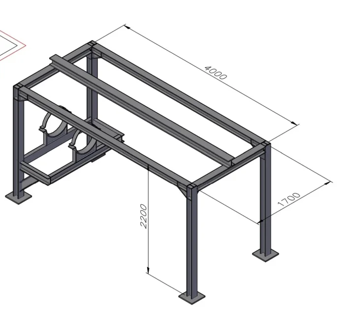
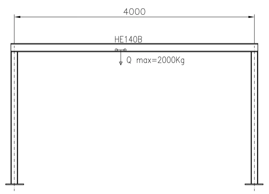
I should check the scope of a heb140 beam material s235, the 2 supports are welded at a distance of 4mt, on 2 plant.
this hoist with wheels, it must be mounted and flows on the lower wing of the heb140.
the hoist has a capacity of 2 tons.
I wanted to know if you have to calculate the size of the wing alone (how?) or just calculate the beam in the classic way of "trave doublely stuck with concentrated load"? !
to better understand I attach the photo:
Thank you in advance
greetings
My question is this:
I should check the scope of a heb140 beam material s235, the 2 supports are welded at a distance of 4mt, on 2 plant.
this hoist with wheels, it must be mounted and flows on the lower wing of the heb140.
the hoist has a capacity of 2 tons.
I wanted to know if you have to calculate the size of the wing alone (how?) or just calculate the beam in the classic way of "trave doublely stuck with concentrated load"? !
to better understand I attach the photo:
Thank you in advance
greetings
.jpg")