You are using an out of date browser. It may not display this or other websites correctly.
You should upgrade or use an alternative browser.
You should upgrade or use an alternative browser.
natered99
Guest
I must realize those circular sections before because in them I have to go to make a tension analysis
F_Ingrasciotta
Guest
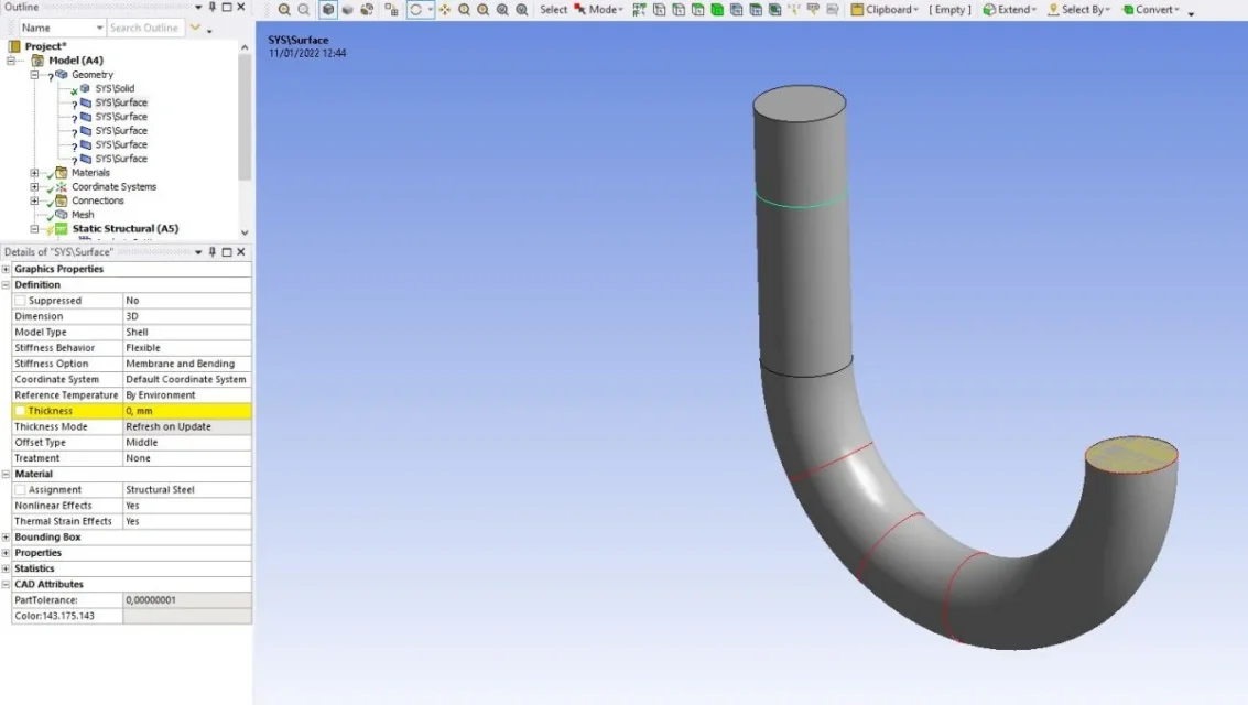
we would understand how you are modeling the problem....to see from the section "geometry" recognized both solid elements and shell elements.
for shell elements you must necessarily define the thickness because, by definition, it is a 2d entity.
I'm afraid your problem comes from the modeling of the hook. try to model on a normal cad and export it as .iges or .parasolid then import geometry into ansys.
for shell elements you must necessarily define the thickness because, by definition, it is a 2d entity.
I'm afraid your problem comes from the modeling of the hook. try to model on a normal cad and export it as .iges or .parasolid then import geometry into ansys.
natered99
Guest
Hello, first of all thank you for the answer.we would understand how you are modeling the problem....to see from the section "geometry" recognized both solid elements and shell elements.
for shell elements you must necessarily define the thickness because, by definition, it is a 2d entity.
I'm afraid your problem comes from the modeling of the hook. try to model on a normal cad and export it as .iges or .parasolid then import geometry into ansys.
Unfortunately for necessity I have to work totally on ansys, even in the geometry of the problem. would you have ideas about how I can solve on ansys?
F_Ingrasciotta
Guest
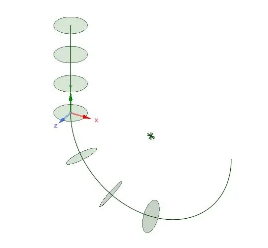
in the second image in the initial post show the hook made by a sweep (?), but since the section remains constant I don't understand why you generated multiple circles.
as the first step, with the current geometry, try to exclude the various shells that are recognized (click above with the right and exclude from the analysis). so doing you should see the whole hook as a solid on which you can generate a mesh.
as the first step, with the current geometry, try to exclude the various shells that are recognized (click above with the right and exclude from the analysis). so doing you should see the whole hook as a solid on which you can generate a mesh.
natered99
Guest
I have put more circles because I practically have the force applied on the circumference of the circle of halfway (the vertical one to understand us) and the other circles that are serving me because after I solve, I have to evaluate the tension on those sections practically.in the second image in the initial post show the hook made by a sweep (?), but since the section remains constant I don't understand why you generated multiple circles.
as the first step, with the current geometry, try to exclude the various shells that are recognized (click above with the right and exclude from the analysis). so doing you should see the whole hook as a solid on which you can generate a mesh.
I am not very practical of ansys so there is probably a more practical solution to my problem, but if I don't put those circles it doesn't make me put the force on the girth of halfway and wouldn't make me evaluate the tension on those other sections I think
F_Ingrasciotta
Guest
the various positions where to evaluate the voltage you can get them simply by dissecting the hook after you launched the simulation.
as for the vertical circle you have to do differently, or define the hook in two semi-million that join in the area
as for the vertical circle you have to do differently, or define the hook in two semi-million that join in the area
natered99
Guest
ah ok thank you so much for all the answers you are giving me, I will trythe various positions where to evaluate the voltage you can get them simply by dissecting the hook after you launched the simulation.
as for the vertical circle you have to do differently, or define the hook in two semi-million that join in the area
F_Ingrasciotta
Guest
I tried to run a model similar to yours to explain better.ah ok thank you so much for all the answers you are giving me, I will try
hook with diameter 5mm and surface cut in correspondence of the halfworks of the curve. applied load 100n.
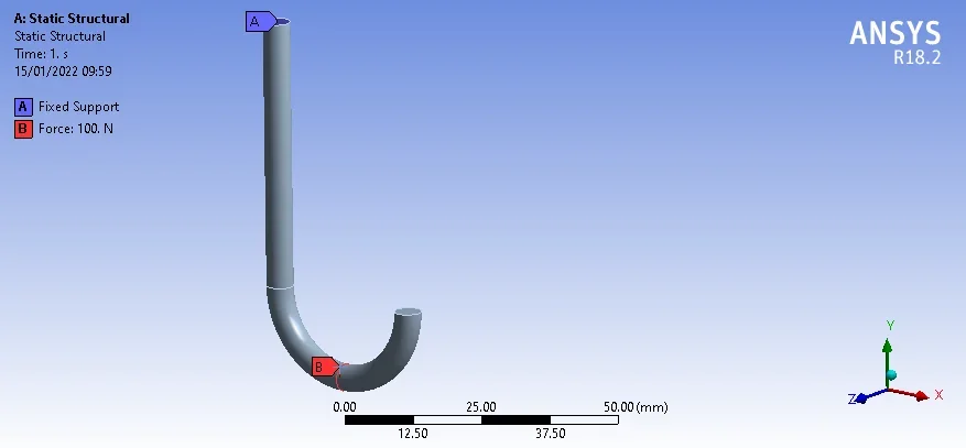
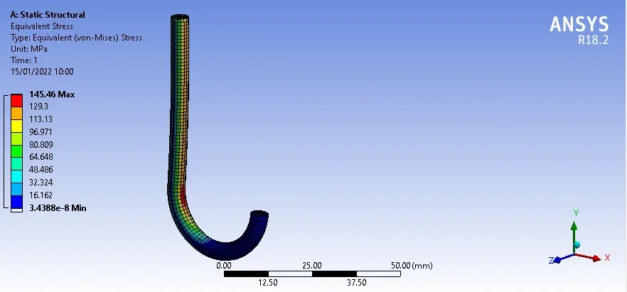 as you see from the half of the hook onwards (after the load) the geometry is completely discharged, condition that fits perfectly to the theory.
to see the sections remembered to cut the surface to the various heights where you want to view the tensions, you can do it with the command "splite" on spaceclaim (so maybe they have different names).
at that point you make a named selection as from image (I cut at 30mm from the fixed surface)
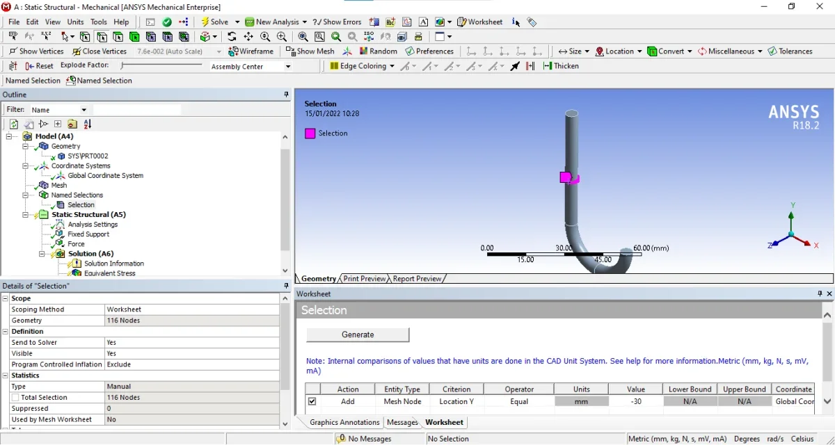 Finally plotted the equivalent stress (vm) only on named selection.
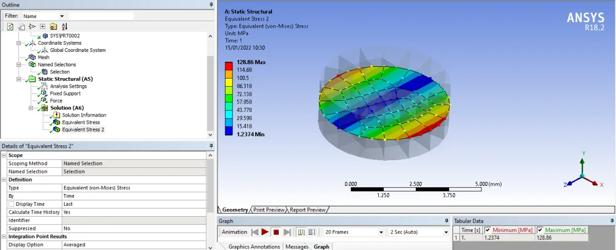 I hope I've been helpful
F_Ingrasciotta
Guest
I forgot about a second method, maybe faster and more effective.
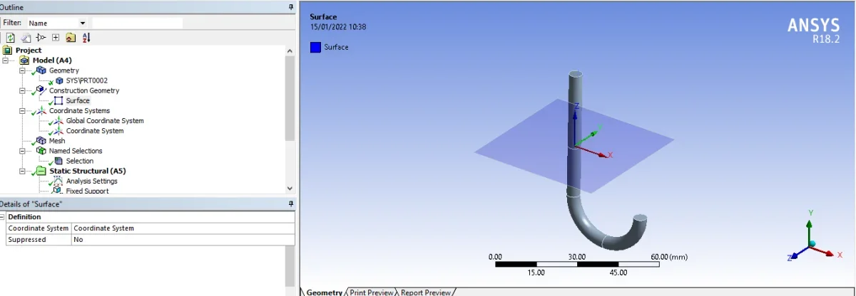
1. define n additional reference systems as many as the sections you want to do (attention to orientation, imagine the x-y plan of section)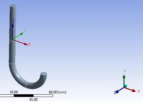 2. right click on "create surface costruction". automatic will create a building surface where you will plot tensions
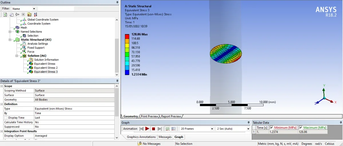
 3. always uses an equivalent stress (vm) but sets it as from below image.
1. define n additional reference systems as many as the sections you want to do (attention to orientation, imagine the x-y plan of section)
 2. right click on "create surface costruction". automatic will create a building surface where you will plot tensions
 3. always uses an equivalent stress (vm) but sets it as from below image.
natered99
Guest
Thank you very much, you were very helpful and kind, really. One last thing, to generate such a precise mesh as you did, did you use any particular setting?I forgot about a second method, maybe faster and more effective.
1. define n additional reference systems as many as the sections you want to do (attention to orientation, imagine the x-y plan of section)View attachment 643422. right click on "create surface costruction". automatic will create a building surface where you will plot tensionsView attachment 643433. always uses an equivalent stress (vm) but sets it as from below image.View attachment 64344
F_Ingrasciotta
Guest
being a simple object just give a length of the set elements quite consistent with the model. so doing will think about ansys automatically to generate a sort of mesh map.Thank you very much, you were very helpful and kind, really. One last thing, to generate such a precise mesh as you did, did you use any particular setting?
natered99
Guest
perfect, thanks for everythingbeing a simple object just give a length of the set elements quite consistent with the model. so doing will think about ansys automatically to generate a sort of mesh map.
natered99
Guest
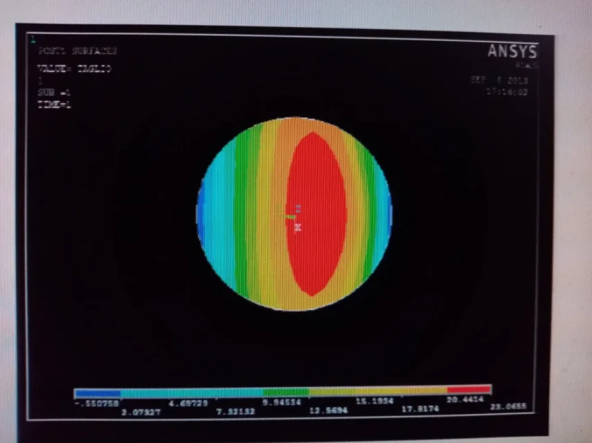
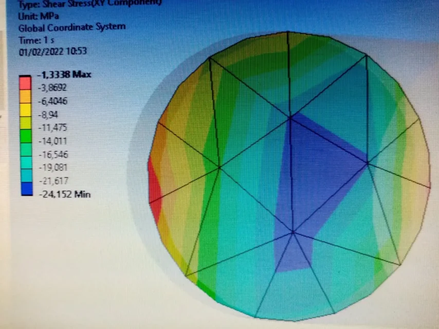
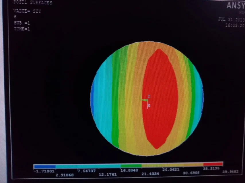
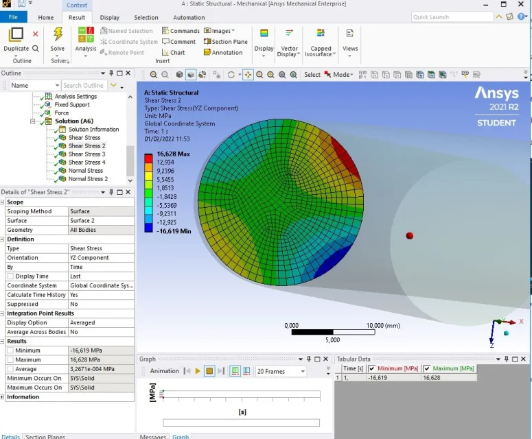
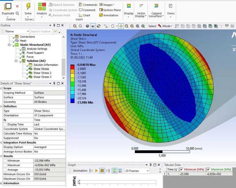
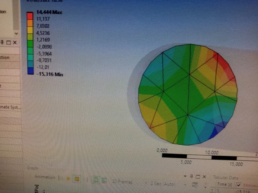 Guys, I still need a hand, sorry. I have attached, with the black background, the results of the tangential tensions that should go out, with white background those, wrong, that go out to me. I reported the results on the vertical section (where the force is applied) and on one of the oblique ones. I can't understand where I'm wrong.
F_Ingrasciotta
Guest
at equal constraints and loads in the two models I could hypothesize a mesh problem.
your mesh turns out a bit gross, try to slightly thread the elements.
Obviously you will never get the same model, because the identical result you only have at equal loads, constraints and mesh (if the problem is in the elastic field otherwise you also have the plastic material).
the less aligned result seems to me the second, try to make screenshots where you read a little better everything....
natered99
Guest
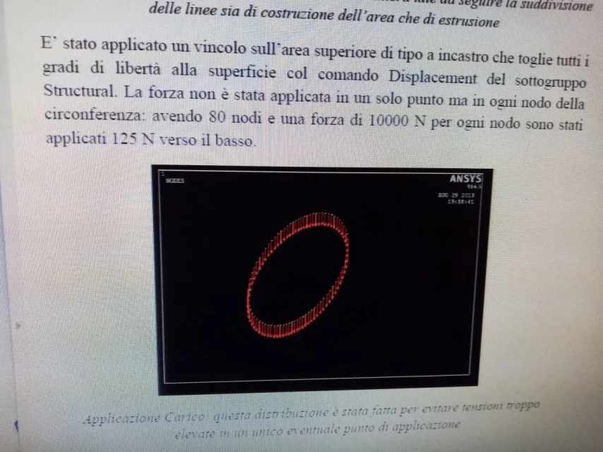
All right, thank you. I practically applied it along the circumference and it is 10000n down. in the file I'm trying to replicate instead, the same circumference is divided into 80 knots, and on each of them is applied a force of 125 n. can that be the reason?
natered99
Guest
natered99
Guest
F_Ingrasciotta
Guest
if the definition of loads and constraints is the same as that of the model you are replicating pays attention to the reference systems of your model and those of the model you want to achieve.
at the moment there are vague info to be able to give you a precise answer (in what exact point is the section that does not return to you? have you replicated exactly the same conditions as the pattern you are taking from? )
at the moment there are vague info to be able to give you a precise answer (in what exact point is the section that does not return to you? have you replicated exactly the same conditions as the pattern you are taking from? )
natered99
Guest
As for loads, I sent the attached photos first, on the different distribution. In fact, my doubt is about that. for the constraints I used the fixed-type bond, in the reference file instead uses displacement, but still gets a recess so I think it is the same.if the definition of loads and constraints is the same as that of the model you are replicating pays attention to the reference systems of your model and those of the model you want to achieve.
at the moment there are vague info to be able to give you a precise answer (in what exact point is the section that does not return to you? have you replicated exactly the same conditions as the pattern you are taking from? )
the sections in which I get really high, are at 30 and 60 degrees of the curved section of the hook

