• This forum is the machine-generated translation of www.cad3d.it/forum1 - the Italian design community. Several terms are not translated correctly.

bearing load

  • Thread starter Thread starter Ing.Vedder
  • Start date Start date

Ing.Vedder

Guest
Hello everyone,
I should size a couple of bearings for a wheel under heavy loads but I would like an opinion.
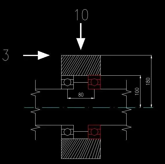
on the wheel (in section) weighs a radial load of 10 tons and an axial load of 3 tons.
the radial load doesn't give me big problems and it also distributes on both bearings.

the axial load instead is applied on the edge of the wheel so I expect that the opposite bearing on the side of the aplication of the load (that drawn in red) receives an amplification of the radial load due to the moments that are established.
in the first line I had reasoned in this way.

moment = 3x180 = 540 [T*mm] therefore 540 [T*mm]/80 [mm]= 6.75 [tonn]in this way there would be a radial load on the most "loaded" bearing of (10/2)+6.75=11.75 ton.

To reason in my opinion is wrong and too cautionary, the arms of moments are not real.


how would you behave to find radial load and axial load acting on the red bearing?


Many thanks to all
 

Attachments

  • untitled.webp
    untitled.webp
    18.5 KB · Views: 76
In the first instance I would worry about seeing if a radial bearing is able to withstand that axial load. usually the skf admits, except for memory error, that a radial bearing can bear a static axial load of up to 25% of the radial load, so risk being out of limits. could therefore be necessary to change type of bearing (already a 2-kron bearing of balls could improve the situation).
 
thor105 thank you very much for the answer, very just observation.
the fact is that to draw the sketch for the forum I simplified the bearing but in reality we are talking about a roller skf bearing, bearings suitable for radial and axial stresses.

Thank you!
 
Why don't you put a normal roller bearing, mounted with axial play, and a brace bearing that does its job to hold the axial thrust? are loads hails, I would not trust "polyvalent" bearings, but I am not expert in the field.. .
 
Thank you very much for the idea. Unfortunately now for design needs the idea of the adjustable roller bearings has been made and cannot go back. loads are remarkable but this type of bearing is able to bear these stresses very well.

My real problem remains as to consider that axial force. I have to report to the client and that's my problem.

Thank you.
 
If I look well at the design, the most loaded bearing is white, not red, right?
Let us first consider the strength, and then the moment from this generated.

the force pushes the wheel to the right, then the tree to the left, then loads the white bearing axially.

then the pair, imagine turning the tree counterclockwise, compared to a board coming out of the sheet. should charge radially in equal measure the two bearings, red at the top and white at the bottom. the central part has a greater section, therefore will suffer a minor deformation, ergo I would transcur the axial thrust due at the moment.

I say nonsense?
 
if I look well the design, the bearing more c
the force pushes the wheel to the right, then the tree to the left, then loads the white bearing axially.
as you say:finger:
then the pair, imagine turning the tree counterclockwise, compared to a board coming out of the sheet. should charge radially in equal measure the two bearings, red at the top and white at the bottom. the central part has a greater section, therefore will suffer a minor deformation, ergo I would transcur the axial thrust due at the moment.

I say nonsense?
I imagined the red bearing loaded radially more precisely because it receives 5 tons of pure radial load ok,
In addition, also receives a upward thrust of the shaft that then sums itself to the 5 tons of load on the bearing (actually the bearing is loaded from above and through the crushed shaft from the center)...my interest was to quantify this load increase. .
the fact that the deformation of the tree is small so radially consider only the 5 tons as well and simple could convince me. .
So all my pippes on the amplification of the radial load go to be blessed. . I think I've been peeing more than I have.


ev
 
It's a big frame that moves. that force is supposed because sometimes this frame can bandage by generating side spins on the wheel. under standard conditions the load is only radial.

Hello and thank you

ev
 
as you say:finger:


I imagined the red bearing loaded radially more precisely because it receives 5 tons of pure radial load ok,
In addition, also receives a upward thrust of the shaft that then sums itself to the 5 tons of load on the bearing (actually the bearing is loaded from above and through the crushed shaft from the center)...my interest was to quantify this load increase. .
the fact that the deformation of the tree is small so radially consider only the 5 tons as well and simple could convince me. .
So all my pippes on the amplification of the radial load go to be blessed. . I think I've been peeing more than I have.


ev
Why 5?
I would see it, 3x180 is the couple generated by force 3

(3x180)/80 are the two equal and contrary forces that are added (radially) to both bearings. these two forces generate the pair that equals that of 3.
 
therefore a radially bearing would be loaded with two forces:

one of 5 tons --> that would be half of the 10 tons radial that I have from the beginning

one of (3*180)/80 = 6.75 tons that is generated by the side force of 3 tons.

in a bearing (the red one) these two forces are added and lead to a radial load of 11.75 tons.

Did I understand?

Thank you.
 
In my opinion, yes, but I wouldn't play parts of the body... it would have to do some free body diagrams by separating the pieces and see if everything "square"
 
fantastic lightning, you answered me at 110%.

a huge thank you for the opinion and help.

ev
 
Hi, I'm in the discussion. ...

I am a technician and I am not a graduate, but I want to make you a practical speech because I calculate every day bearings (design and design gearboxes) and I want to do the simplest and most practical things:

know the loads... know the bearing positions, well I would go up: www.skf.it , I would register at the skf site and once registered you can use their own program for calculating the binding reactions (knowing the data mentioned above) and once also chosen the type and size of the bearings calculate their duration.. .

I would do that, indeed every day I do this. .

Good day
 
wow gragario, thank you! explain where I find the program for binding reactions!?
on the skf site I had just escaped!
I present the calculation section where you can calculate duration static and dynamic load bearings etc but the part for the binding reactions I just missed!

Thanks for the tip!! I'll go check it out now.

ev
It's like, http://www.skf.com/skf/productcatalogue/jsp/calculation/calculationindex.jsp?&maincatalogue=1〈=itand then here: http://webtools.skf.com/bearingselect/frames.jsp?lang=en

ciao
 
typically these free providers programs are as simple as they are effective. ..they take into account practically everything, the only problem is that the result is an element of the supplier catalog...but in case of skf I don't think it's a problem.

Good idea!
 
It's really cool.

great link, thank you so much to you and to fulvio my companion of elucubrations. :biggrin:

ev
 

Forum statistics

Threads
44,997
Messages
339,767
Members
4
Latest member
ibt

Members online

No members online now.
Back
Top