• This forum is the machine-generated translation of www.cad3d.it/forum1 - the Italian design community. Several terms are not translated correctly.

bending radius in relation to sheetmetal thickness

  • Thread starter Thread starter makeng
  • Start date Start date
the k factor is set in the material, for the rest, you can manage it with the relationships
 
Welcome back to all. I wanted to submit a problem that I have and I didn't find trace in the forum: the fold rays related to the thickness.
Usually proe sets radius=thickness, but it is a technological error since the bending blades usually have radius or 0.8 or 3mm. normally folds with internal radius of 0.8 up to 3 mm thick including , and 3mm internal radius from 3 included up (usually up to 10 mm or max 12mm). I then compute the development I abandoned the calculations and I entrust myself to a folding table of the slaves.
what would be important is not to set all times manually the radius, but to have it default set with those criteria I described earlier. Is that possible?
Thank you.
makeng
the problem of the 'lamieres' is dealt with in many forums, perhaps somewhat dispersive (one mention here and another there).
in all these discussions there is the problem of thickness, bend radius and infamous factor k.

Now, given that no cad calculates the deformation of the sheet neither at least represents it, the ways to 'calculate' a development are basically two:
a neutra line saying and the other I call a correction factor.
with nx I set these formulas independent of the fold radius and the thickness with which the piece is modeled:
p.e. with these formulas if the lengthening of the processed sheet is of, suppose 1 mm for each fold, the formula works 'a retrose' i.e. calculates the factor k that gives me the correct development.

for what concerns instead the setting of the fold radius values I can not enter the merit of a cad that I do not know, in my case imposed by default the fold radius equal to half thickness but I could put it also 5 times the thickness that would give me the development 'that I want', even if the piece is not like what would exit from a fold press.

a=0 //se =1 calculates according to ln
fc=if(a=1)(5*(2*(rp+sp)-(rp+sp*ln)*pi()/2))lse(kp)
k=(fc-rp-sp)*(-2/rad(90)-rp)/sp
kp=xxxxxxx //correct factor to be set according to experimental data
In = 5/12
rp=sp/2

Sr=sp+rp


I hope I've been clear

Hello everyone
 
I fully agree with baskets,
However for those who want to manage the internal radius of fold in a different way, type bb

1 to 2.5 ret = 1
3 to 4 ret = 1.6
5 to 6 ret = 2

I think of a pretty practical system:
change > set > parameters
give the right value to the smt_dflt_bend_radius parameter and save the table. repeat the operation for all desired thicknesses.
at this point when you create a new part just load the right table and in the features of extrudes, flange etc. indicate the radius of curvature "by parameter".
I hope I've been clear.
Hi, dani,
but what version do you use? I can't find the directions you give me....

bb
 
I fully agree with baskets,
However for those who want to manage the internal radius of fold in a different way, type bb

1 to 2.5 ret = 1
3 to 4 ret = 1.6
5 to 6 ret = 2

I think of a pretty practical system:
change > set > parameters
give the right value to the smt_dflt_bend_radius parameter and save the table. repeat the operation for all desired thicknesses.
at this point when you create a new part just load the right table and in the features of extrudes, flange etc. indicate the radius of curvature "by parameter".
I hope I've been clear.
Hi, dani,
I really didn't know this screen......:tongue:
Basically in the value column, I'm gonna load all the rits I need, right?
When I make a sheet, I'll find them dishonable, is it correct?

I hope I can understand it once and for all this speech on the plates because it creates a lot of difficulty. :confused:

bb
 
yes, when you create a sheet load the file with the right parameters and the game is done.
If you need, you can check the other parameters, not just rit.
 
yes, when you create a sheet load the file with the right parameters and the game is done.
If you need, you can check the other parameters, not just rit.
I tried with a relationship to assign the value smt_dflt_bend_radius through a parameter in turn related to the thickness of the sheet, but the result is negative..... possible that you can not?

and then at this point the columns
attribute
car/man
report
yes/no

What are they for?
It can be that I wrote something wrong....I'm going to memory....:biggrin:

bb
 
Hey, bb,
to learn more consult online help, where there are many news.


"information on default settings and sheet metal parameters
default settings and sheet metal parameters allow you to automate routine tasks to facilitate part project optimization. to ensure consistency within the project and save time, you can pre-defined some of the most common feature geometry components, thus reducing selection operations from the menus.
default and parameter commands allow:
● Define new default settings and new sheet parameters for a part or project or use the recover command (retrieve) to apply default settings and existing parameters.
● modify existing sheet metal parameters using the edit command (edit).
● Save and store in the directory the sheet parameters file (.smd) using the save command (save).

the difference between a default value and a parameter:
● parameter - contains a numerical value that can be specified in relationships and formulas.
● default - reduces the number of selections of the menu.

you can set default values and parameters when you open the part for the first time or import an independent .smd parameter file. default settings and parameters are saved along with parts, but their values can be changed during the session. "


p.s.
neither did I manage to assign a value to smt_dflt_bend_radius through relationships, perhaps the only way to set it is through the setting file
 
I am sorry to check that unfortunately you cannot set the inner diameter according to the thickness of the sheet. Among other things it is important above all because this type of setting reflects what happens in carpentry: the operator decides the matrix and the punch according to the thickness and type of material and always maintains it as "technological culture" of the carpentry itself. I know that the solid edge is possible to do it and I do not understand why a software like I create does not. we hope the ptc is listening.... .
 
I am sorry to check that unfortunately you cannot set the inner diameter according to the thickness of the sheet. Among other things it is important above all because this type of setting reflects what happens in carpentry: the operator decides the matrix and the punch according to the thickness and type of material and always maintains it as "technological culture" of the carpentry itself. I know that the solid edge is possible to do it and I do not understand why a software like I create does not. we hope the ptc is listening.... .
Why do you say you can't do that?
If you use the tables of the bending parameters, as described above, just load the right one and get the result you want.
 
Maybe... I'll tell you what's the problem seen from the end: after creating a sheet part create a flat wall folded. What internal radius does the system propose? to me equal to the thickness. then, it is true, go over the value of the proposed radius and appears the browse of all possible rays in the table. But I ask you, what happens if I forget to do this? and if by chance step from a piece with thickness 2 to one with thickness 4, the internal radius must pass from 0.8 to 3mm for all folds, otherwise (and here is disaster) the developments are wrong. Of course I am talking about precision carpentry, not lattonery. for me to make "sensitive" the internal radius according to the thickness of the lameira is essential to avoid problems. I know that with solid edge you can do it. and it also applies to many other specialized software for sheet metal.
Thank you
 
if creating a flange or extrusion wall gives it as an internal radius by parameter takes the right values that you have uploaded according to the thickness and if you change them automatically update all the internal rays of all the folds of your piece.
 
Sorry, I don't understand. you say I should set somewhere a variable that imposes me "internal link equal to parameter". But I don't know how. Can you explain it better? What I would like to avoid is to choose the internal radius every time. so that the program reads the thickness and proposes the radius in the corresponding table.
Thank you.
 
no, you do not have to set a variable, you have to make the choice by parameter in the feature options, see image.
in this way the internal radius is set to the value of smt_dflt_bend_radius, and changing it updates all the folds
 

Attachments

  • Immagine.webp
    Immagine.webp
    73 KB · Views: 30
Okay, and that's clear. but how can I set the ri= 0.8 mm for thickness from 0.8 to 3 and re=3mm from 3mm up? This rule also depends on the equipment of the carpentry (!) and I often find myself in difficulty because each carpentry follows its logic of equipping. I would see that somewhere there was:
if thickness = 0.8
then radius int= 0.8
if thickness = 1
then radius int = 0.8
if thickness =1.5
then radius = 0.5
....

if thickness = 3
then ray int = 3..

as I can succeed if the rule smt_dflt_bend tells me only = thickness, =2*spessore etc.. ?
Thank you.
 
as I can succeed if the rule smt_dflt_bend tells me only = thickness, =2*spessore etc.. ?
Thank you.
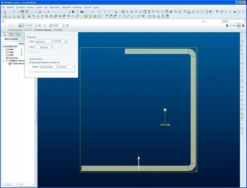
to the smt_dflt_bend_radius parameter you can also manually assign the value you want, which will become the default value when you choose "by parameter" within the various features.
 
I'm sorry if I'm insistent, have patience and don't send me to that country. I don't get what you say. When I create a new wall (flat or flange that you want) on internal radius, the values of the bending table connected to the part (default by default.prt). and then I have to select the radius. Maybe I have to create so many defaults.prt as many as the thicknesses?
thanks to patience
I'll let you know.
probably just use a start part with correct relationships.
 
I'm sorry if I'm insistent, have patience and don't send me to that country. I don't get what you say. When I create a new wall (flat or flange that you want) on internal radius, the values of the bending table connected to the part (default by default.prt). and then I have to select the radius. Maybe I have to create so many defaults.prt as many as the thicknesses?
thanks to patience
Good morning,
Don't worry, I have so much patience, at least how many people have taught me how to use cad.

no, it is not necessary to create so many standards.prt, but many folding tables, one for each thickness, and to load them immediately after creating a new part:
change > set > parameters > open and load the right configuration file for your thickness with internal radius, coefficient k etc.
 

Forum statistics

Threads
44,997
Messages
339,767
Members
4
Latest member
ibt

Members online

No members online now.
Back
Top