• This forum is the machine-generated translation of www.cad3d.it/forum1 - the Italian design community. Several terms are not translated correctly.

board on sheet board.

  • Thread starter Thread starter Zimmemme
  • Start date Start date

Zimmemme

Guest
Hello, I have a question.
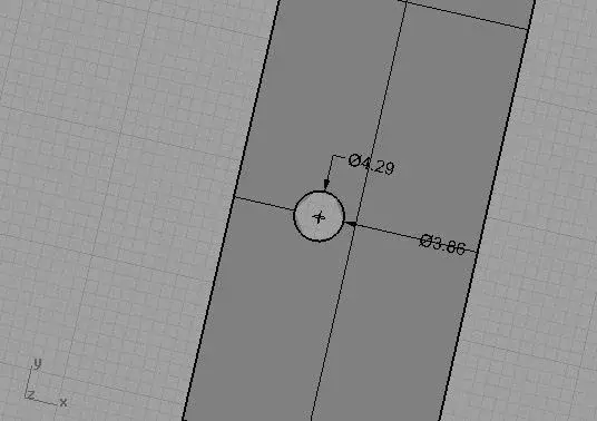
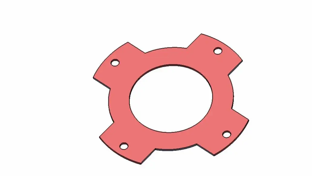
I have a sheet made of steel for " deep funnel" of circular shape with a hole in the center and four small perimeter holes in diameter 4.
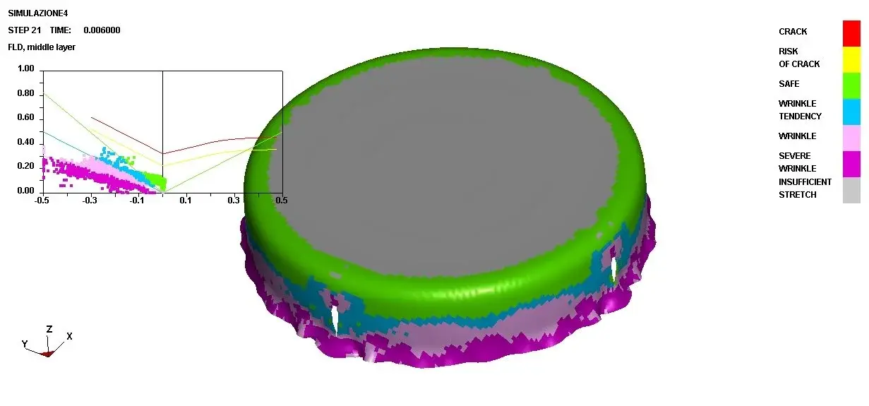
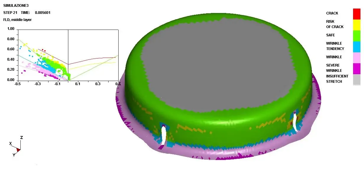
If I had to put the figure out how much the holes would deform?
I attach the iges file of the model both before and after the funnel.
The model is approximate and only serves to make it clear where I leave and where I want to get there.

Is there a way to minimize hole deformation?
do you notice how to move the holes or change the diameter?

thanks in advance for the answers.
 

Attachments

Double curvature surfaces are not developable if not with cuts and approximations

in other words... You don't want to realize that whole thing.


rhino spits this sentence, developing the side wall tape;
or holes after bending the sheet, but it does not suit.. otherwise cut an ellipse -5% (two/three tenths on 4mm)
 

Attachments

  • cad3d_37.webp
    cad3d_37.webp
    15.6 KB · Views: 33
Thanks a million for the quick answer.
no, no holes after the funnel or fold it is.

But I don't need holes to be perfect.
from what I have understood therefore the hole would only be worth 0.3?

How did you calculate the ovalization of the sheet with rhino?
 
boys, a minimum of order and method, please.

there is a special area that deals with molding and there is a regulation that invites "caldely" to respect the thematic topics of the various areas. :mixed:

would be good creativity and also index of far-sightedness to post questions like the one above in that area.

ossequi:smile:
 
thanks for the clarification.
I've been lying here and I haven't found the right place.
If the moderator can and may want to move the topic.
 
Bye.

according to my experience I can tell you that in the company where I work we have printed similar pieces, in some aspects more critical, since the model you posted has a good relationship between the diameter of the cylinder (60) and the height of the flange (11) so as to allow to obtain the shape imbuted in a single passage, while we happened to have to print pieces where at equal diameter the flange was also 40 mm so we had to predict more
the development in plan of the figure, due to the double curvature of the piece will necessarily have a margin of error; These problems usually solve them in the mold test phase, measuring from time to time the result obtained and modifying the initial 2d development, this also regarding the deformation of the holes, and finally on the flanged walls will easily arise of the clutches.
other considerations that can be done, are for example the type of sheet, the type of mold that you want to use (simple or double effect), the possibility for example to print the piece and maybe to cut it later by 3d laser cutting (so all holes and flange height would be ok).
According to me 0.3 mm of ovalization are a bit of a force, it is probably the error calculated on the holes, assuming to cut the flange from the top and then develop the latter in the plane.

tvi71
 
tvi71it said:
According to me 0.3 mm of ovalization are a bit of a force, it is probably the error calculated on the holes, assuming to cut the flange from the top and then develop the latter in the plane.

tvi71
Just what I did. .

In fact I have no experience on this type of sheet metal processing, but I can't imagine that the flange can be made in that way without wrinkles!

:confused::confused:
 
Okay, but how much could the hole deformation be?
someone in my company told me that a diameter 4 could also pass to diameter 12! ! !
possible?
 
But no, come on. unlikely to be optimistic.
with the files that I posted, so, from complete neophyte, I don't think they deform more than a millimeter.

Or not?
 
Hello, everyone.

As I had some free time, and these days it's not so strange, I allowed myself to do some molding analysis of the piece in question with the simulator we have here in company.
This confirms my assumptions made in previous posts, but especially to try to resolve the question put by zimmemme.
I attach two images of the results.
I have made two hypotheses of mold:
- traditional mould composed of stings, matrix and external primer that holds and accompanies the sheet during moulding. at the premier I gave 5 tons of pressure, while the sheet is a fep04 commonly used in vehicles with good printability characteristics. the initial development is that of zimmemme without the big central hole, this because it deforms so much so as not to allow even the forming of the piece. in any case the image highlights the goodness of the formed piece (green-gray zones) but the lateral holes were severely deformed. the raggetto at the bottom evidences how the starting development remained of the excess material in addition to the end of the flange following the ironing of the sheet during the molding phase.
- mold like the other but with central primer and use of the same parameters. in this case, during the molding phase, the part of the central plane is held by the primer, but the flange sheet enters the matrix as it seems and the final result is that on the flange there are wrinkles (blue/pink/violet). Also in this case the side holes are severely deformed.
Concluding, it results from the analyses carried out that it is possible to obtain a well formed piece and perhaps optimizing the initial development it is possible to obtain the flange with the correct height, however regarding the punctures these should be realized in a phase after the forming.

tvi71
 

Attachments

  • Simulazione_Premilamiera_Centrale.webp
    Simulazione_Premilamiera_Centrale.webp
    37.1 KB · Views: 36
  • Simulazione_Premilamiera_Esterno.webp
    Simulazione_Premilamiera_Esterno.webp
    41.7 KB · Views: 39
curiosity: what software generates that graphic analysis?
there are many, are molding simulators, used to see before throwing money into the construction of a mold, if the piece is feasible and what defects will turn out, giving the opportunity to improve the math of the mold in order to obtain then an optimal result.... some of these that come to mind, used x the automotive industry and not only, are: pam-stamp, autoform, dynaform, altar ... etc.
 
I think something's wrong.
I agree with the first hypothesis, which is then that of the second image.
I also agree with the second on the fact of the clutches.
It's on the holes I have doubts.
I think the simulation is not correct.
However, I have no way to prove it so I just have to accept it (thank you very much).

Suppose we have four perimeter carvings ranging from the outer perimeter to the center of the figure.
in this case would the holes be better?
I don't know why, but if I imagine bending the wings with the clamp, I guess the holes don't get so low.
Am I right?

Good simulation!
 

Attachments

  • PARTENZA-1.zip
    PARTENZA-1.zip
    16.1 KB · Views: 7
  • PARTENZA-1.webp
    PARTENZA-1.webp
    14.2 KB · Views: 8

Forum statistics

Threads
44,997
Messages
339,767
Members
4
Latest member
ibt

Members online

No members online now.
Back
Top