• This forum is the machine-generated translation of www.cad3d.it/forum1 - the Italian design community. Several terms are not translated correctly.

calculation stress and bending sheet metal deformation

  • Thread starter Thread starter Cast16
  • Start date Start date

Cast16

Guest
Bye to all,

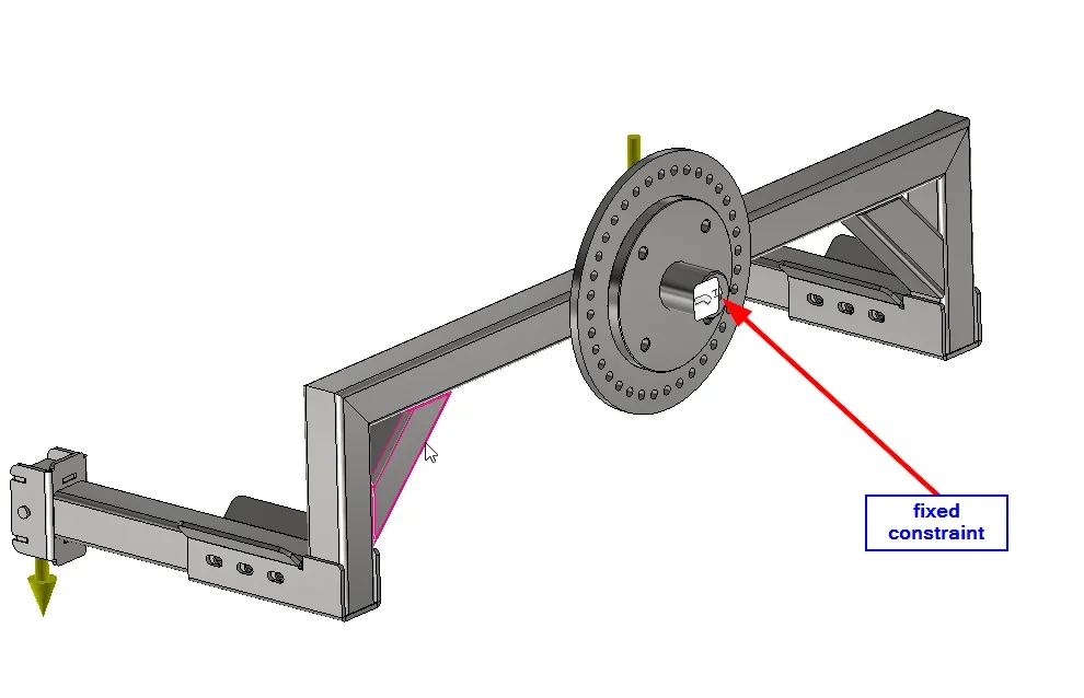
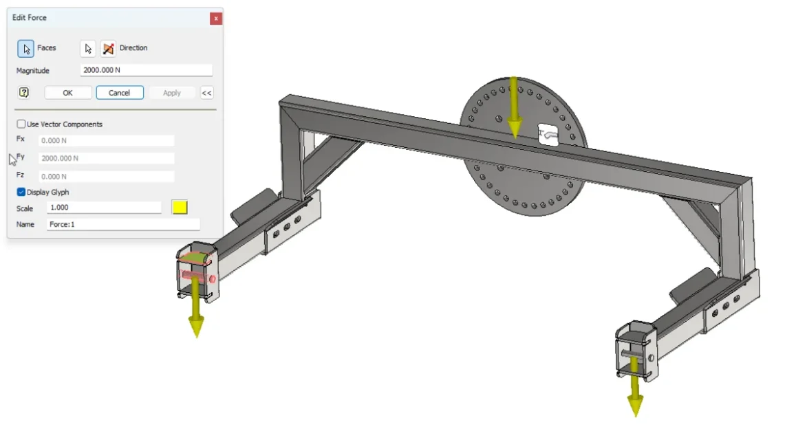
as from title, how to calculate the max stress and deflection of the folded sheet section (s275 thickness 5mm section 45-60-45mm) with 200 kg weight as in the attached photo. everything will eventually be tested and certified by an external consultant, but I am trying to test it with fea of inventor in the design phase. are in the first weapons with fea, and the completely different results between stress analysis and nastran are not helping. I wanted to see what the results of manual calculations would be.
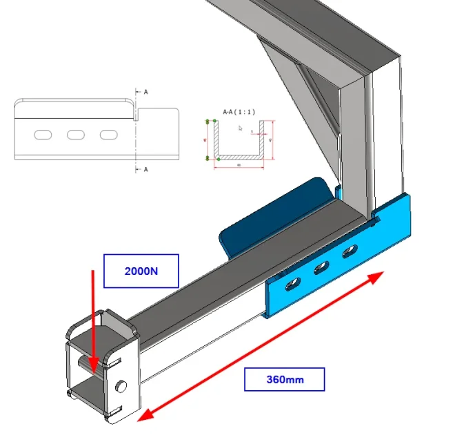
2023-01-30 06_17_17-2023-01-27 11_13_24-Autodesk Inventor Professional 2021.png ‎- Photos.webp
 
for a maximum calculation you can idealize your profile as a beam stuck with concentrated load, remote. clear that where you have folded discharges there is a stress concentration, as there is a carving.
Consider that we are not evaluating the stiffness of the rest of the body, so we are in case worsening. that is, we are assuming that the tubular tract is infinitely rigid, which is not true of course.
If you want to do a good job, evaluate the rigidity of the tubular body. but in this case I would go directly to fea.
 
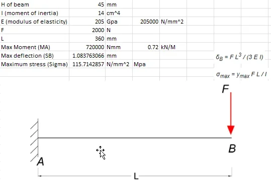
Thank you. News That's what I tried and gives me 116mpa and 1mm deflection.
but stress analysis me from 868mpa and 11mm deflection.
So I thought my calculations were incorrect. Can you give an occiata to the below screenshot?
2023-01-27 11_19_18-IREQ FOR UDL(UNIFORMELY DISTRIBUTED LOAD) BEAM.xlsx - Excel.webp
 
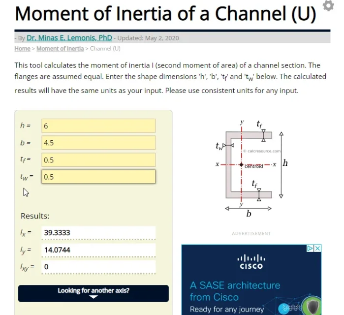
1_Is it safe that the moment of inertia is correct?
2_you don't have to take everything that tells you the calculation software, you have to be able to set the calculation and be able to interpret the resulates.
if the manual calculation is correct you cannot have 868mpa, because you must consider that in practice it is as if you consider your beam with a twist spring, which indicates the rigidity of the tubular system, then the voltage will be lower, and the shift greater. if we consider the carvings, near them there will be a high gradient of effort, but not so high as those that indicate. could be the result of a numerical singularity. You have to see.
 
for the moment of inertia I used this: link. screenshot attached.

This I am thinking too: the results cannot be so different. one of the two (or both) are wrong. not having studied this, I was wondering if there is a way to calculate manually and what results would have had someone here in this forum that maybe knows how to interpret the results.2023-01-30 07_31_45-Moment of Inertia of a Channel Section _ calcresource.png
 
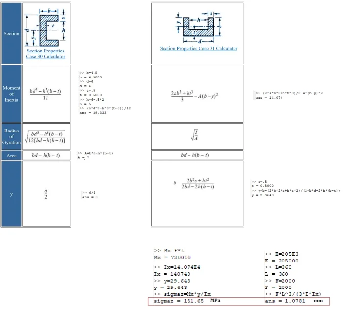
finite elements do not take into account a lot of things that instead fall into beam theory; according to me better manual calculation, should be much more reliable (the area moment is definitely correct). 1675080008982.webp
 
you have to calculate the centerpiece with varignon for example, then the moment of inertia with transposition theorem.
you can use a cad to calculate the moment of inertia of a section.
however the calculation of the moment of inertia of superifice is correct.
finite elements do not take into account a lot of things that instead fall into beam theory
e viceversa
according to me better manual calculation, should be much more reliable
depends on what you mean. is not a clear and correct statement.
 
finite elements do not take into account a lot of things that instead fall into beam theory; according to me better manual calculation, should be much more reliable (the area moment is definitely correct).View attachment 67602
Thank you. @davidex e News It seems my calculations weren't bad. after putting the precise value of the i and changed the y (I had simplified b/2) I had exactly the same values. I try to deal with the fea.
 
We're talking about the correctness of a finite element analysis... and there's no analysis.

You just need to check the blue component, don't you?
You imported all the asses into the fem? if yes, how are the contact constraints between the various components?
otherwise how did you represent the fact that the load is not actually applied on the blue component but on the gray beam?
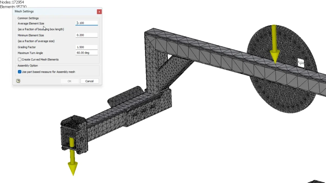
Mesh, are you okay?
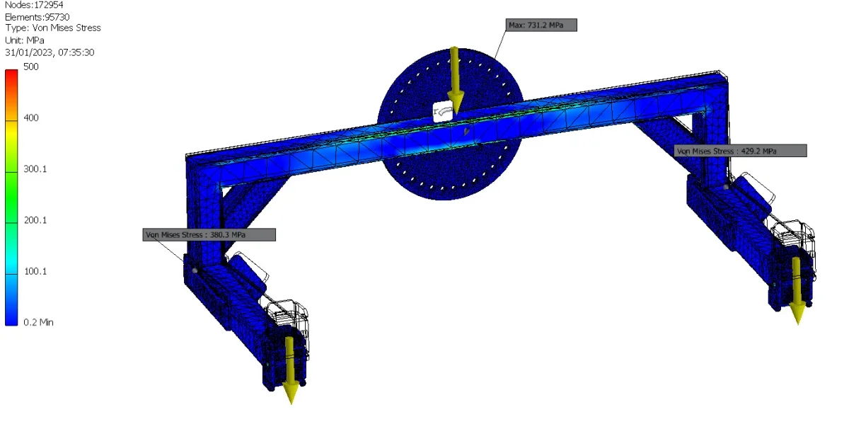
I am max stress of 868 mpa where is it?
@stan9411 I've tried all the help. all bonds are bonded. max stress gave it to me where I expected it, in fold drains.

Now it's in the horisontal tubular. If you want to give an occiata, the attached report.

screenshots:
2023-01-31 07_32_22-Autodesk Inventor Professional 2021.webp2023-01-31 07_34_38-Autodesk Inventor Professional 2021.webp2023-01-31 07_35_11-Autodesk Inventor Professional 2021.webp2023-01-31 07_36_08-Autodesk Inventor Professional 2021.webp2023-01-31 07_36_46-Autodesk Inventor Professional 2021.webp
 

Attachments

from the images you uploaded is evident how the structure is all discharged (practically all blue) so the peak of 731 mpa is the son of a singularity (imputable to 3d or mesh).

the traverse mesh is very gross at first impact.

I would say that more detailed images can help.

classic university exercise was to analyze individual components and not the axieme to bypass the problem of constraints that very often are difficult to shape. make a pattern of balance of the individual components and then make the fem only of those.
 
Bye. according to the problem is the rod modeling stuck with shelf with concentrated load in an extreme, given the geometry... a rod stuck with 360mm arm shelf and 200kg load at the extreme is wrong; You should consider the total arm 360mm + what goes from the bond, so you will have a total arm longer. I think, for example, that may be 700mm (eye), so it would be:
f = 2000
l=700 mm
== sync, corrected by elderman ==
ix = 140740 mm^4
= 29.643 mm
and = 205000 mpa
= 294.87 mpa
= 7.9256 mm
 
Last edited:
Then,
As for the efforts, I see a scale going 0 (blue) to 500 (red) mpa. then the model is all on average blue/blue/green.
the points you have highlighted with stress of 731 and 429 mpa, are evidently points of instability of the calculation.
it is not possible that you have a mesh knot at 700 mpa and then all adjacent knots in the color range between 100 and 300 mpa
 
Second, as others are saying to you, if you simulate the whole structure, it is clear that your maximum arrow point will be greater than the hand calculation of the single beam. practically what in hand calculation was an ink, now it is a yielding bond
 
Bye. according to the problem is the rod modeling stuck with shelf with concentrated load in an extreme, given the geometry... a rod stuck with 360mm arm shelf and 200kg load at the extreme is wrong; You should consider the total arm 360mm + what goes from the bond, so you will have a total arm longer. I think, for example, that may be 700mm (eye), so it would be:
f = 2000
l=700 mm
== sync, corrected by elderman ==
ix = 140740 mm^4
= 29.643 mm
and = 205000 mpa
= 294.87 mpa
= 7.9256 mm
is not clear to me the finding of davidex (why 700 mm? in the drawing he says 360 from the load to the vertical beam)
but it gave me the point for my observation.@ cast16 Did you do it by applying the inertia time of the profile to u at all 360mm? but the sheet is long only about half....
 
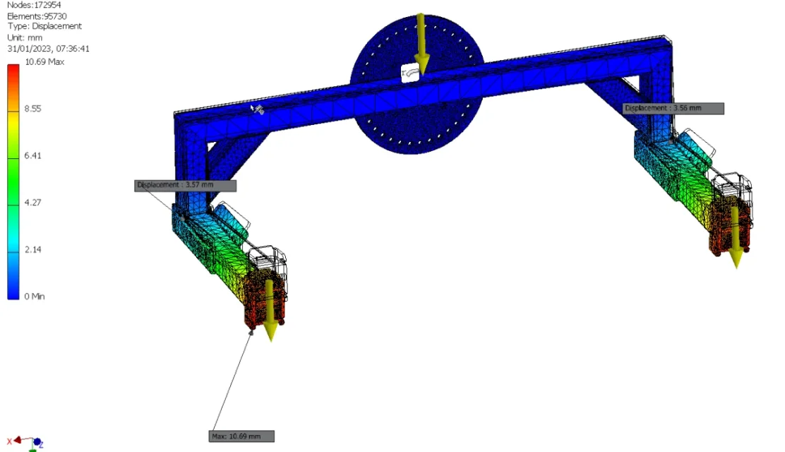
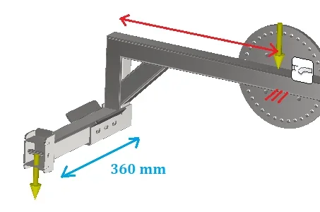
the simulation is quite different from the model to the first message, with rod set of 360mm and load concentrated at extreme by 200kg (in which it would be about 150mpa and 1mm displacement). It's clearly not good for geometry. so you could consider a curvilinear rod and approximate it to a straight length (I hypotize myself to the eye about 360mm plus other x mm see fig in red). It is a very forced approximation that is absolutely not good to calculate the longitudinal internal tension to the profile (because the moment is distorted), but could instead give an idea of deformation. 1675171992989.webp
 
thanks to all for the time and advice.


My situation is, I'm not an engineer, I'm struggling to break down forces, and when I can, I don't feel safe. Since I have two fea included in the inventor, I try to analyze an assembly that I expected to be simple (in the end it is not so simple). lego 2 guides here and there, I look at the tutorials, I try all the two fea (nastran and stress analysis) but the results are completely different. I try to make the calculation by hand of the part that I expect to be the weakest point (simplifying much the situation), and the result is different from the first two.

I know I'm going off topic but the company where I work is offering me to do a nastran course with the author of the book "up and running with autodesk inventor nastran". This person seems to be concerned that a person should not be an engineer, and in 2 days of course I would be able to fea. I'm a little puzzled. believe me I have tried different mesh, changed also the settings of convergence, but I have had even more high results.
 
but... in many companies who do structural simulations, that's all. and it takes years to become capable.

definitely doing a course is a good base to start from. . but not enough to know where the buttons are to be pressed for the specific software. . You have to be aware of some physics and mathematics behind it... If there is a knot at 700 mpa in an area of a thousand knots at 300 mpa, it is sure a meshing error ... I'm going to ask about cad3d.

However returning to topic, first it is not to mix apples with pears.
do the fem on the individual component, paying attention to the type of constraints and goodness of mesh. the number that comes out from there you appear with the calculation by hand.
then add complexity
 

Forum statistics

Threads
44,997
Messages
339,767
Members
4
Latest member
ibt

Members online

No members online now.
Back
Top