• This forum is the machine-generated translation of www.cad3d.it/forum1 - the Italian design community. Several terms are not translated correctly.

centrifugal fan installation

  • Thread starter Thread starter Hope1
  • Start date Start date

Hope1

Guest
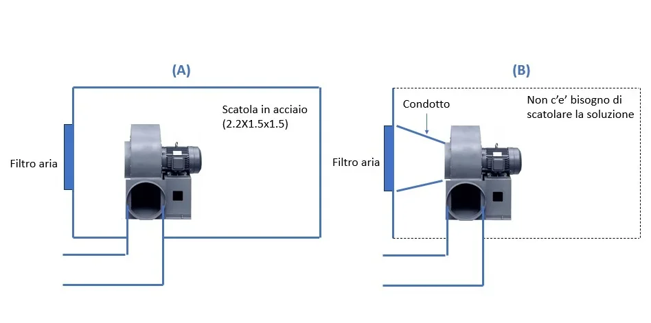
Good morning, I have a question about installing a centrifugal fan (motor about 30kw).

the solution (b) with duct between vesilar input and filter and without external box was challenged.
The solution (a) has been told to me is better - but no one has the time to tell me why (and I am not expert at all I would like to understand).

according to me:

(a) creates vacuum in the box increasing the load losses in input to the fan and the steel box increases the weight of the machinery where it is to be installed.
(a) I don't understand if the electric motor is well refurbished.

(b) does not have (a) problems
(b) requires more attention to mounting for tolerances etc.
(b) the load on the duct between filter and veniler can be elevated by vacuum effect

If (a) is a typical installation for industrial fans I make one reason and step by step - I just want to have a second feedback from you.

thanks to all (even only for reading the message).
 

Attachments

  • Ventilatore centrifugo - installazione.webp
    Ventilatore centrifugo - installazione.webp
    15.7 KB · Views: 42
bho, always seen b, maybe with limited duct. to only in case of need of soundproofing, but the maintainers after removing it do not put it back
 
bho, always seen b, maybe with limited duct. to only in case of need of soundproofing, but the maintainers after removing it do not put it back
Hello chicken,

Thanks for the answer. Let's see if there's someone else who wants to answer.
or (b) I'll still be happy to be doubtful!
 
this question is very interesting and your observations are legitimate.
We keep in mind that centrifugal fans, like this, should be mounted in the channeling.
in the type to the channeling of input there is not, therefore it does not create true aspiration.
in type b a short channelling, but conical and convergent towards aspiration.
If the diameter of the filter is double the aspirator input diameter, the aspiring capacity is reduced by 1/4, if you have to aspire fumes, you wouldn't succeed.
in a hood it is possible, only because the hood itself conveys them upwards.
Let's hear what you think. Bye.
 
Hello, Marco, thank you for the answer.

in the installation I'm following the centrifugal fan is used to send cooling air to electric motors but I understand what you say with the example you made of the hood. only to give dimensions, in my case the surface of the filter is about 4 times that of the input to the fan,

the connection between the filter and the fan I put it in the solution (b) because I would avoid boxing that part of the machine but also because I've never seen a similar installation - I admit I have zero experience about it.
I am not very experienced in this matter, but like you I would do the b solution, for all the considerations you have made, unless it is a question of aesthetics / design.
 
the two functional solutions are equivalent, the difference is the type of use and the environment in which they are installed.
the choice solution represents a Dumped blower which, in front of a higher cost, offers a more pleasant aesthetic and is easier to clean, in addition to the possibility of reducing noise if the sound absorbent panels are applied to the interior walls of the cassone and vibrations with the help of antivibrants.
 
I think that, since the fan activity is preemptive (and not aspiring) with the solution to you have the dual advantage of protecting and soundproofing the aspiration, there is not to make the moving parts inaccessible to the operator.
If the fan instead was used for suction, it would be necessary to connect it directly to the pipe to eliminate some types of losses.

for fans in box, there are specialized companies, or even the main manufacturers offer a production service of loudspeakers.
 
Thanks to you too, Teo. one of the things that is known in the images of the chest fans who shared the transctor is that when the engines are not mounted outside the box, they are always placed between the air input in the box and the fan input. I suppose they position the engine so as to maximize cooling.
 
I usually use only fans, bins, but connected both in and out (my process is dimensioned in suction).
in that case the engine is positioned in the back and exploits, in addition to the motor ventilation car, or a servo ventilation (also pushes air outside the box) or a natural ventilation with staggered vents.
in an application with suction inside the box, it can make sense to do as you said but only for heavy applications
 

Forum statistics

Threads
44,997
Messages
339,767
Members
4
Latest member
ibt

Members online

No members online now.
Back
Top