• This forum is the machine-generated translation of www.cad3d.it/forum1 - the Italian design community. Several terms are not translated correctly.

cylindrical tank size

  • Thread starter Thread starter cccicccio
  • Start date Start date

cccicccio

Guest
Good evening, everyone.
is my first experience of sizing a cylindrical tank (horizontal) that will contain water products. its diameter is about 2.9m and will have a length of 7m. the funds will be decinormal of the same thickness of the cylindrical surface. the tank will be in aisi 304. Can you help me calculate the thickness that should have the wall? the cylinder will not be in pressure
 
We remain in the context of a pre-dimension and above all we say that I am expressing opinions. So I might be wrong.
begin to assess the maximum traction (we prevent seismic speech and horizontal loads). in reality is placed about 90% of the depth and therefore about 6.5m deep.
without wanting to do pharmacists you can safely consider the maximum traction at the bottom.
the traction force of a parallel is therefore: ps*h*r (highly oversized) where with ps idium the specific weight, h the total height of the liquid and r the radius of the tank (in fact I applied the famous formula of mariots).
if you have water then the maximum strength will be: 10*7*(2,9/2) = 101.5 kn/m
normally for variable loads of the tanks the amp coefficient of the loads is 1.3 and not 1.5.
the safety coefficient for steel is usually 1,05 for current elements and 1.25 for knots and for particularly weakened parts.

if I don't remember the asi304 has a yield value of 190 n/mm2.
therefore, for a unitary strip and admitted not to use reinforcements and considering not to have particular dynamic amplifications:
minimum thickness = 1.3*101.5 / (190/1,05) = 0,73 mm.
But I'd increase it a bit. by making some speculation you might think of increasing it at least 2mm in the parts where dynamic effects are important (type in a hopper even if it is not your case) and increasing it by 1mm to consider the amalgamation.
I mean, maybe I wouldn't go down under the total 2mm thick. but it's my consideration.
try to search on the web some company that makes tanks and see if you find the indications of the thicknesses so much to understand if they increase them for reasons other than structural calculation.
if you want to put a reinforcement you can decide to assign the traction force entirely to him or you may decide to share it proportionally to stiffness or areas.
I admit, however, that I have no experience in the sizing of this type of tank.
I usually calculated tanks of a decidedly larger size but with structure in c.a. / c.a.p.
It is probable that for a steel tank it is necessary to foresee horizontal and vertical reinforcements both to contain the thicknesses and both to avoid any phenomena of instabilization (it is not to exclude that under the weight precisely with too reduced thicknesses you can have this problem). it could also be worth doing a part of the tank with the maximum thickness and the remaining with a reduced value (to be calculated at the altitude where you decide to change thickness).

However if you want to deepen the seismic speech try to take a look here:
Thank you for the solicitation you answered.
the tank in question is cylindrical and placed horizontally (the axis of the cylinder is parallel to the ground). will be mounted on appropriate supports but in this first step we do not consider.
will be something like the photo.
 

Attachments

  • cisterna.webp
    cisterna.webp
    14.7 KB · Views: 9
yours is a building that must comply with the regulations in force and in the national and international field you can identify a large number of codes and regulations that specifically treat the project and construction of cylindrical tanks with circular section; in particular:
Eurocode 3, part 4 – uni-en 1993-4:2007: design of steel structures -
silos, tanks and pipelines.Eurocode 8 part 4 – uni-en 1998-4:2006: design of structures for
seismic resistance - silos, tanks and pipelines

I tell you some of the many resources you can draw from.the cousin is a collection of rules and various calculation procedures in pdf format collected in a zip file.the second is a master's thesis (rednimum, pdf), of a graduation of the polytechnic of Milan, on tanks in vertical welded steel with variable thickness (in your case, given the size and being horizontal, the thickness could be uniform), which extends besides the calculation also to the structural analysis and current regulations.

see if you can be useful.
 
Thank you for the solicitation you answered.
the tank in question is cylindrical and placed horizontally (the axis of the cylinder is parallel to the ground). will be mounted on appropriate supports but in this first step we do not consider.
will be something like the photo.
Damn it, I made it all wrong.
I would try to consider the problem as a plan in deformations before I stepped up with a finite element calculation program.
In practice I take a central ring of typically unitary or adequate width (e.g. the one between two supports) and the ground ink (then the loads are self-balanced for hydraulic pressure and therefore the couple and the horizontal force in the bond will have to be about null).
At this point I have to solve a simple circular ring frame. The symmetry is enough to consider half a ring.
the horizontal load varies linearly with the height (from zero to the fur superior to the maximum value given by the height of the liquid for the specific weight).
possibly take the average value of horizontal pressure or even maximum pressure (procedure recommended for tubes buried by an old French regulation to simplify the thrust of land).
if you do not want to make too many accounts, just a simple program as a frame2d of the ice cream to evaluate the stresses in the ring.
find the tensions of the ring will be enough to multiply by the ratio of poisson (typically 0.3) to evaluate the tensions that run parallel to the axis of the reservoir.
then, possibly I would also make a trave check for vertical load (water weight and an estimate of that of the tank) between two consecutive supports in the longitudinal direction of the tank.
also analyzes a small portion of limited width. as the tank was formed by many independent striscies (although it is not true). Actually, like every tube, to do things properly you should analyze it as a elastic beam on an elastic medium (winkler) where the springs are given by the contribution of the rings that form the tank.
and finally remains the analysis to the finite elements with elements of type plate / plate (guscio).
In short, I would proceed so much to have an idea of the behaviour of the tank.
then refer to the indications that gave you tetrastore even if maybe I would add to use a more detailed text like that on plates and shells: "design the shells. steel, reinforced concrete and precompressed. plates, tanks, domes, paraboloids and pipelines. gravity, instability and seismic actions" of limes g. michele roberto nascimbene published by iuss press, 2011 or why not, the old belluzzi, perhaps volume 3. texts that you will surely find in the library.
Of course that describe only in words the procedure...for a technician it is almost tiring to read and understand. Wasn't a box better and less words?

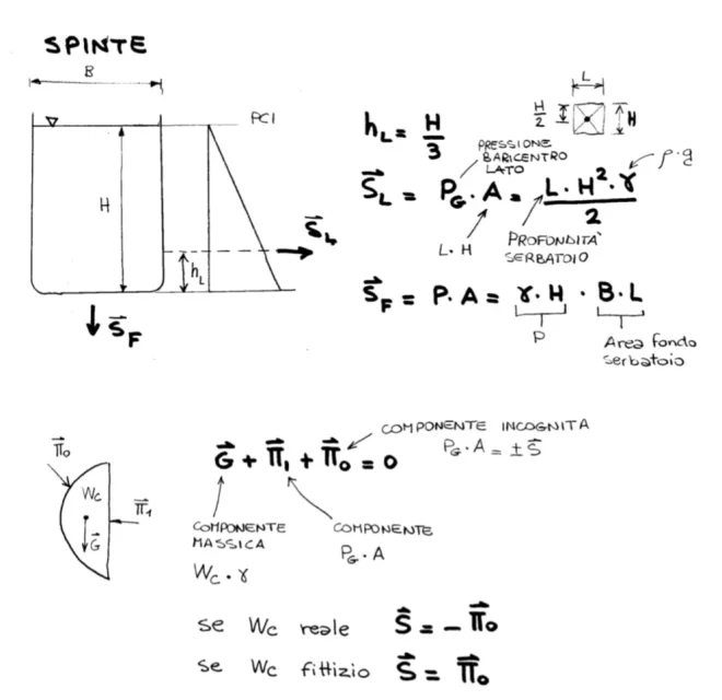
However a non-pressure tank has the strains generated by the liquid as follows:Screenshot_20210929_210812.webpClearly all this is a very academic way to solve everything.
the only professional solution is to follow the rules that have indicated you in the previous post.
Of course, trying for the first time in something like that is not really easy.
 
for that diameter and length you should stay on 4-5 mm thick.
I read that the reservoir contains aqueous products, verify the compatibility of the 304 axis, keep in mind that e.g. Innox fears chlorides.
 

Forum statistics

Threads
44,997
Messages
339,767
Members
4
Latest member
ibt

Members online

No members online now.
Back
Top