• This forum is the machine-generated translation of www.cad3d.it/forum1 - the Italian design community. Several terms are not translated correctly.

design for wheels

  • Thread starter Thread starter Jockettino
  • Start date Start date

@mario sjpd

I apologize for the question that will be silly to you, but the mouth that I have highlighted serves to have a greater surface of support keeping a carpentry of reduced thickness?
1658213700312.webp
 
but the question remains, why do you block the pin axially and in rotation in two points? One is enough. Why do you create a ring around the drum so important? that importance for the good operation of the machine the coupling between the tilted planes wheel and ring seems very precise , I would do two shoulders rights on the wheels but I would leave a little air unless a precise positioning is indispensable, maybe the shoulders I would screw to the wheel that would start flat and the drum would apply only to the wheels moving leaving free the drum to slide on the wheels (and not just sliding the contact part).
 
Last edited by a moderator:

@mario sjpd

I apologize for the question that will be silly to you, but the mouth that I have highlighted serves to have a greater surface of support keeping a carpentry of reduced thickness?
View attachment 66112
exact the bushing is welded to the carpentry ear and then worked, the pin sticks and locks to the rotation translo with that simple plate
 
Last edited by a moderator:
cadinpiedi, I don't know what you mean in the last part of the post where you're suggesting to hold your back, can you please explain to me?
Good evening, I think you'll have understood that I meant welded shoulders or ears that you'd like:)
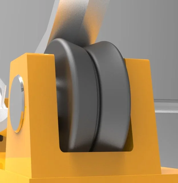
However for clarity, you said that to allow the dilation slide you thought of using a sintered bushing so that the wheel scrolled on it, well but finished the heating cycle the wheel would not go back! and the next time it would continue to move coming in contact with the ears with consequent grip.
for this are better the bearings blocked by the spacers, the wheel does not move on the pin and just an air of 5 mm.
the slip takes place on the two contact circles of the wheel and the ring. Consider that it is a very slow interaction, before the drum reaches the 160° it takes at least 20 minutes, maybe these days... much less seen the lower delta t:), so on the wheel and ring it takes the graphite fat.
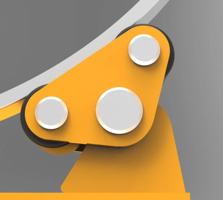
But be careful that you need a good carding, both for safety reasons, and to prevent the malt pulviscle from clinging with the fat by creating intersections that would trigger vibrations.
 
Moreover the two pairs of wheels will have different tasks, the nearest one as much as possible to the chain transmissison should be the fixed point and the other the sliding point.
also consider that on the engine side support also acts the chain throw that increases the loads!
I have seen that to make a fixed point you have foreseen a wheel with v shoulders, but as you have drawn the ring would strip against the throat with razing friction, better avoid and conform the wheels and the ring with V contact as from image below:
 

Attachments

  • Supporto_post.webp
    Supporto_post.webp
    13.8 KB · Views: 8
Have you ever been in the queue behind a cement bidder? if you look well you will see that they use two oscillating supports with four wheels, so:
Thus the centering is better and the loads divided between multiple bearings and the surface on which the sled ring is increased.
I agree with mario sjpd about the choice of shielded roller bearings with a pair of nilos rings and greased through a central hole of the pin.
 

Attachments

  • Supporto_ant.webp
    Supporto_ant.webp
    19.7 KB · Views: 8

Forum statistics

Threads
44,997
Messages
339,767
Members
4
Latest member
ibt

Members online

No members online now.
Back
Top