meccanicamg
Guest
of my excel sheet for gears... more than 600 hours work..... when I have time I add and implement.pictures you see are from an excel sheet.
of my excel sheet for gears... more than 600 hours work..... when I have time I add and implement.pictures you see are from an excel sheet.
la technical specifications are the performance and operating characteristics of the shocker. can be found in household appliances manuals as reported before. morphological matrix of the mechanisms does not tell me anything except a political parolone. I believe it is the choice and discussion of why of the endless screw that breaks with two counter-rotating wheels etc.maximum calculations and choice of materials. would mean that you set the formulas in excel so that you have the formulas that subsequently automatically provide you the results including the conditions of control with the formulas "if this is greater or equal to....then". do not think to take an admissible sigma a priori and then look for the material because you have as the field of choice of all steels treated and not for the screw then loads of breakage from 300mpa to 1500mpa and for the wheels you have all steels, all bronzes and brass, all plastics for a traction break from 80mpa to 1500mpa. Moreover there are incompatibility of coupling of materials and incompatibility with types of lubricants.It's a year project and it's organized like this: technical specification, morphological matrix for the choice of mechanisms and components, maximum calculations and choice of materials on the basis of maximum calculations.
therefore the materials must decide after the calculations of maximum according to the required performance.
I thought I would assume a value of sigma adm, calculate the module and repeat and then use that value of sigma adm found to choose the suitable material. I was thus organizing a sheet of excels. Maybe I can take values for verification and then after the choice of the material checks permanently.
The aim of our professor is to make us think and try not to block us from what has already been done and I must admit that a slasher is not the best choice in this sense but I have only realized it in the full of the project? I will try to do my best for calculations, thanks for the advice.
Can I ask you the pictures you showed me are from a program?
design of plastic gears according to kissoft.This interesting self-referential seminar, organized by kissoft in February 2020 at the Milan Polytechnic, shows the evolution of the regulations in this area, but highlights the many limitations that still exist in order to make a certified calculation.Surely we are very out of classical computing standards and we should understand if there are specific regulations that can help us with plastics.
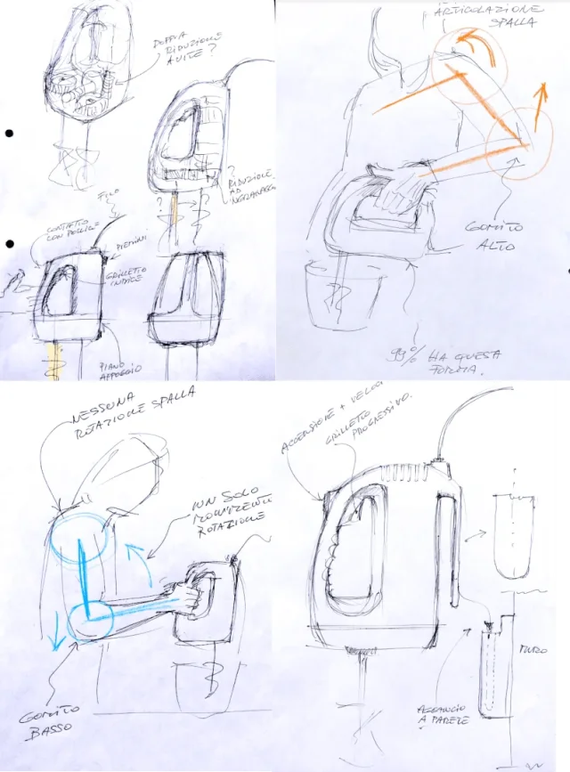
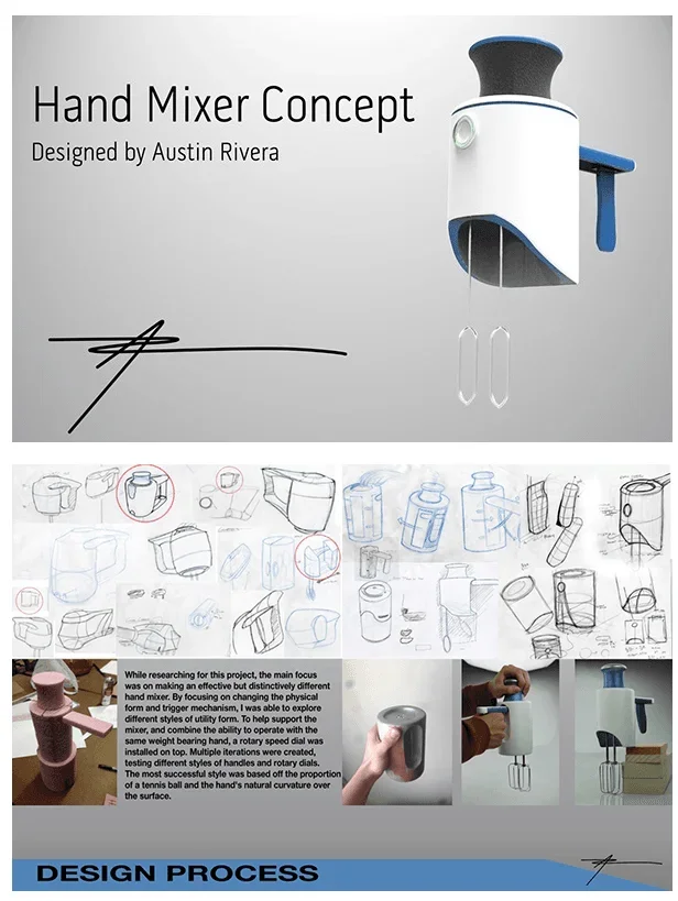
I think the solution is definitely innovative and valid from the ergonomic point of view only if the tool is kept vertical.this means that it has been refined by hundreds of attempts and the most convenient mechanical solution is obviously this. However ergonomically it does not convince me, the lady luisa with a slight principle of arthritis, when it has to knock the eggs must move the joint of the shoulder to lift the object holding the high elbow, while if you could grab the tool with a front handle would do less fatigue, and then through an accessory bracket could hang the sbattitore to the wall.
In my opinion, the solution seems really convincing, but we must also take into account the psychological aspect that can affect the market. people are now accustomed to that type of design and also to the movement, although it seems a great idea from the point of view of a designer and a magai engineer can not be seen of good eye. then I think that in order to tilt to maybe put more strength you move anyway a little bit the shoulder.I am perfectly aware that this is the forum of designers, and not that of designers. with a small search on the topic you can find hundreds of models...all equal, or better having the same identical layout. this means that it has been refined by hundreds of attempts and the most convenient mechanical solution is obviously this. However ergonomically it does not convince me, the lady luisa with a slight principle of arthritis, when it has to knock the eggs must move the joint of the shoulder to lift the object holding the high elbow, while if you could grab the tool with a front handle would do less fatigue, and then through an accessory bracket could hang the sbattitore to the wall.
How does the cinematic chain change with this layout? I don't know, I make the designer, engineers will think about it... and marketing has approved


with this system I think you can maintain more stability of maneuver and you will probably get less swinging vacuum.In my opinion, the solution seems really convincing, but we must also take into account the psychological aspect that can affect the market. people are now accustomed to that type of design and also to the movement, although it seems a great idea from the point of view of a designer and a magai engineer can not be seen of good eye. then I think that in order to tilt to maybe put more strength you move anyway a little bit the shoulder.
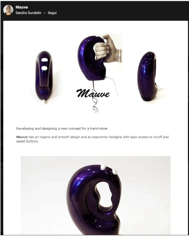
in the case of my project I entrusted myself to reviews and asked friends and relatives to be able to make a list of needs to be respected, and no one brought this kind of problem afloat so I kept myself to classical design. But I found an interesting project of a designer. instead she has taken into account mostly of the movement of the wrist, and I am considering it in the final idea of layout. Would this type of handle be more uncomfortable than usual?View attachment 62409
 So things are two:
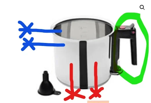
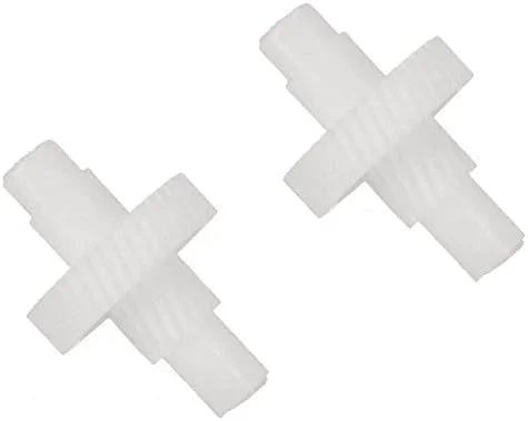
do not have the curvature because obtained from molding and the curvature would be a subsquadro. so are also the engine crowns that are typically used for wipers. as someone said, these products have a really low usage frequency, so they are not sized to get endless life.. .further observation: looking at the internet exchanges of different brands there is no endless screw wheel with classic curvature.View attachment 62412So things are two:
- or are helical wheels with skewed axles
- is an endless screw and wheel with dot contact because the wheel does not embrace the tooth of the screw but only at one point, significantly worsening mechanical capacity
There's something to investigate.
Well it is a light and limited operation over time and luckily not everyone has arthritis like Mrs. Luisain the case of my project I entrusted myself to reviews and asked friends and relatives to be able to make a list of needs to be respected, and no one brought this kind of problem afloat so I kept myself to classical design.
 in the industrial reality the field is dominated by the Chinese components, as indicated by tetrastore in the link to alibaba where you see the standard motor:
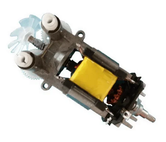 that is nothing but the one drawn by the Swedish university that I linked.
observing the three positions of the hands, in particular the central one, from the finger position we can consider the presumed diameter of the device of about 40 mm.But I found an interesting project of a designer. instead she has taken into account mostly of the movement of the wrist, and I am considering it in the final idea of layout. Would this type of handle be more uncomfortable than usual?
trying to make calculation with khk gear calculator, we immediately bump into the rotational limit where more than 24000rpm does not allow to enter. for the geometric characteristics it limits again to little more than 3000rpm considering the steel screw and the wheel in nylatron mc901 or higher quality (pa6 series).just to have an idea of greatness put you what happens with conventional materials:View attachment 62403Surely we are very out of classical computing standards and we should understand if there are specific regulations that can help us with plastics.
 so we can start from these dimensions to evaluate the rest of the mechanics.
to size the screw you must keep in mind that the contact is dotform if the screw is not and globulidal or even if it is in all cases it is but more extended to the contact surface then for checking to wear the wheel I recommend you to apply the method of dot contact taking into account the strong heating of the wheel on the screw so as not to grip...Hello everyone, I just signed up.
I'm a student at the master of mechanical engineering. I'm designing an electric shocker and I have to do the maximum calculations but I don't know where to start. I chose a brushless motor and a transmission with endless screw and wheel. the only since I have is the speed of the whips then of the wheel that reaches up to 2000 rpm. I have assumed a number of teeth of the wheel of 40 and the number of principles of the screw pairs to 1, through the transmission ratio I found speed of the screw and therefore of the motor of 750o s^-1 = 72000 turns/min. I think it's very big as value because the power of this kind of appliances is about 400w, you think it's okay or I'm wrong somewhere?
while for the design of the endless screw can I proceed as for normal rotisms? that is through a iterative calculation then calculation mt, sigma adm, transversal module with formula of the helical wheels, ray of the screw, peripheral speed of the screw and remake everything until I find values of the module close to the unified one.
I don't know if I've asked too much or different topics? I hope it's okay
