• This forum is the machine-generated translation of www.cad3d.it/forum1 - the Italian design community. Several terms are not translated correctly.

design short but wide ribbon, which makes bridge between two ribbons, food environment, feathers at both ends.

  • Thread starter Thread starter max2
  • Start date Start date
I work with montech.com and also offer a support service to the designer. prices are competitive and quality is excellent. also possess compact solutions and engines in rollers.
 
beautiful company especially very well advertised compared to our Italian companies.
The only product I've seen is this:Screenshot_20190908_151339.webphas very small diameter rollers in the head but surely there is not much to invent. being postponed to the head you can approach the big rollers, but this is a normal technique used on small carpets.
If you want, you can also mount dentate straps on 10/15mm diameter pulleys. but you will never reach 5 mm in diameter. If you want to use hardened steel pens you should do the channels to make compressed air fluid suspension both to decrease friction and to dispose of friction heat....but it becomes very arduous.
so according to my experience there is only the vibrating plan to be able to use at zero geometry.
 
Good morning to all colleagues.
I am not very experienced in tapes (or is it said carpets?) of transport, and I find myself to draw one that, without special attention, they tell me will not stand on track.
If someone has experience, even some simple advice would help me a lot.
Thank you.
I describe the monster.

must transfer bulk food, from oven, rather friable, from a tape to another tape. both tapes have rollers of diameter large, 150 and 240 mm diameter. their centers are 500 mm. mat widths : upstream 850 mm and downstream 820 mm. that downstream has also containment edges. the minimum speed is 2 m/min and the maximum 4 m/min.
1. therefore need a pen on the entrance side and a pen on the exit side, not to present a step too high to climb (inlet side) or to descend (outside side). the distance between the ends of the pens is about 460 mm; These pens should be stripped, with a 2.5 mm radius, for a thickness of 5 mm of the material (inox) of which the pen is made. the mat (or ribbon? mah?) should be 794mm wide and its development should be on 1100mm.
I am carefully rereading your post, trying not to propose different solutions but trying to optimize what you requested.
- the motorized roller must be trunkconic and if you can't do it head you have to do it on an intermediate windingScreenshot_20190908_154249.webp- the pen can not have radius 2.5 but something more, as attached, must be cooled, in rectified cementing material or with bombed rollers in the centerScreenshot_20190908_154359.webp- use little winding angle on the pens and so much on the motorized roller to give right grip force for friction
- use little tape tension and self-regulating tensor
- use more or less impregnated fabric tapes but are of low thickness and for food use as length 212tcw wrapping on a minimum roll diameter 15 mm
- ensure proper full-load retirement using the systems indicated by the ribbon manufacturerScreenshot_20190908_155621.webp- often to make pens with non-stripping elements use ball bearings or needles or igus bronzines in plastic material (the most suitable)
 

Attachments

read all messages. very interesting all. Obviously opinions are not all agreed (if they were to be concerned), but in the end I learned a lot about how to make ribbons. on how not to do them.
I thank mechanicalmg for suggesting the linear vibrator. indeed it would have many advantages from the cleaning point of view, but the customer puts me a stop because it says that the product is too delicate and could not suffer half a meter of vibrations. and we don't have a way to prove it.

I also understood why experts do not recommend you all but all to do great winding corners around the pens. It took me some time, but I finally got there. I thought it was the usual foundationless rumor, as there are still in mechanical design (a hard to die says that the inertia of a motor should not be too small if compared to the inertia of the load to be rotated/translated).
The reason is friction. the more the winding angle is greater the friction force is great. the thing is similar to the rope wrapped around a tree. They also call it the Argan law. In short, if you try to pull a car out of an envelope by pulling a rope wrapped partially around a tree, you don't have to wrap too much this rope around the tree, otherwise the force that you will exercise in pulling the rope will go almost all to win the friction of the rope on the tree and will not remain almost anything to pull the car.

thanks to all colleagues and good evening.
 
I also add that especially with very small feathers increases the more stressful winding the flexible.
as you have already been told for traction use an appropriately sized lower roller
 
but beyond the donkey back rollers and blasphemies there are other ways to make tapes straight?:roflmao:
an infallible way is a fife type guide,
I saw a tape with a guide that corrected the parallelism of a continuous roller,
Obviously it worked perfectly.
I couldn't memorize because I couldn't dwell and the less I could photograph.
This system was very small, very compact, and operated on a food line.
chapeau!
 
stupid question, since I imagine that the possibility has already been examined and rejected, but why not laterally mate the new tape to the 2 existing tapes, making 2 turns to the material with special guides?
Perhaps to better treat the problem of the difference in altitude the new tape will have the shape to "z", presenting 2 sections, which will be those that welcome the curves, and a section downhill, that previews to recover the difference in altitude.
 
an infallible way is a fife type guide,
I saw a tape with a guide that corrected the parallelism of a continuous roller,
Obviously it worked perfectly.
I couldn't memorize because I couldn't dwell and the less I could photograph.
This system was very small, very compact, and operated on a food line.
chapeau!
What is a fife guide? some kind of active tape tension control system?
 
What is a fife guide? some kind of active tape tension control system?
a fife or emg system....that are two brands of well-known builders who make driving systems using different principles, which can be magnetic, laser, x-rays.
They are normally used for paper coil, sheet metal, plastic film.
we use them only when the customer gets impunta that wants the brand...but we have developed much cheaper systems that guarantee the same precision adjusts.
we also mounted on a carpet a roller with a cylinder for part that derails it from the opposite side the carpet. we have two close lasers rotating on a center so you can decide the reading tolerance window.
 
I intend to deviate the flow of the transported material, I attach a scheme for clarity. although, perhaps it is unenforceable if the material is too friable
 

Attachments

I intend to deviate the flow of the transported material, I attach a scheme for clarity. although, perhaps it is unenforceable if the material is too friable
it is used for bottles the staging.
for those products the front pens since they do not go in Indian row
 
with an active tape guide (fife or other or self-built) if the tape is "intrinsically " wrong in its proportions (width/length ratio, pen size, profile and angle of roller winding) is not that the problem solves it: You leave him behind, who will always be there to correct.
a self-constructed tape guide, if it does not have a drive with a well done program (I don't say a real pid, but you don't have the sure cable with simple timer to damp the reaction to the signal that detects on/off the breakout) after a while it doesn't make it anymore and begins to react too much to the bandages ( inevitable with the measures you indicated initially) .
If you have a product to carry fragile, as I feel I have understood, you also realize that if you get dirty the rollers....mandating straight the tape becomes even more tougher
 
hello to all, I regret the discussion for a question concerning rotating feathers.

I have to fix rotating feathers made as an attached pattern: or the shaft is supported by a pair of ball bearings per side. such a shaft and bearings are subject to breakages (the shaft breaks on the joint of the bearing for fatigue) . I would say that the problem is caused by excessive tension of the tape that causes an overload on the bearing and shoulder. beyond this I doubt that the pattern of the two bearings is correct.

I imagine that those who built the system having to remain in the radial encumbrance of the shaft were forced to put small bearings and thinking that the resistance of two attached bearings added gives a double resistance of the single bearing. I schematized the system as a double recess and analyzing what happens within the double attached bearing I see that the force resulting from the contribution of the moment transmitted to the bearing is much greater than the resulting. therefore it seems that a system of constraint of this type stiffens excessively the tree, striving both this and the bearings

Do you think I correctly schematized the problem?
 

Attachments

  • IMG_20211016_174926.webp
    IMG_20211016_174926.webp
    33.8 KB · Views: 26
Have you thought about eliminating the break zone, the shoulder, and making the tree smooth?
shoulders on the bearing housing and blocks the axial movement of the tree at the end with rosettes, wreaths, seggers. .
 

Attachments

  • Immagine.webp
    Immagine.webp
    15.3 KB · Views: 29
the smooth tree I can't do it because as I said above I have to be with the radial encumbrance to about the size of the tree I attach a clearer design so that it can be understood better.
mine was a question to understand if it is correct to think that double bearing only does damage.
However to solve the problem I am increasing the diameter of the pen from ø25 to ø30 mm so as to have to pull in a reduced way the tape (which I repeat has certainly been strained too much by the customer), increased the section of the tree where there are the bearings (from ø10 to ø15) and put of the bigger bearings, moreover I am passed from a tree in butter (aisi 304) to one in duplex.
 

Attachments

  • IMG_20211017_181447.webp
    IMG_20211017_181447.webp
    22.6 KB · Views: 15
the smooth tree I can't do it because as I said above I have to be with the radial encumbrance to about the size of the tree I attach a clearer design so that it can be understood better.
mine was a question to understand if it is correct to think that double bearing only does damage.
However to solve the problem I am increasing the diameter of the pen from ø25 to ø30 mm so as to have to pull in a reduced way the tape (which I repeat has certainly been strained too much by the customer), increased the section of the tree where there are the bearings (from ø10 to ø15) and put of the bigger bearings, moreover I am passed from a tree in butter (aisi 304) to one in duplex.
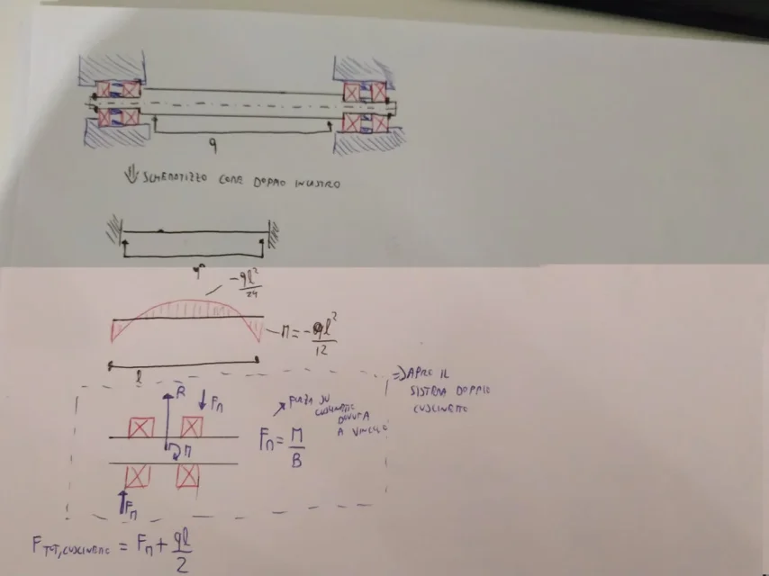
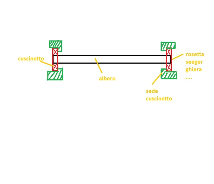
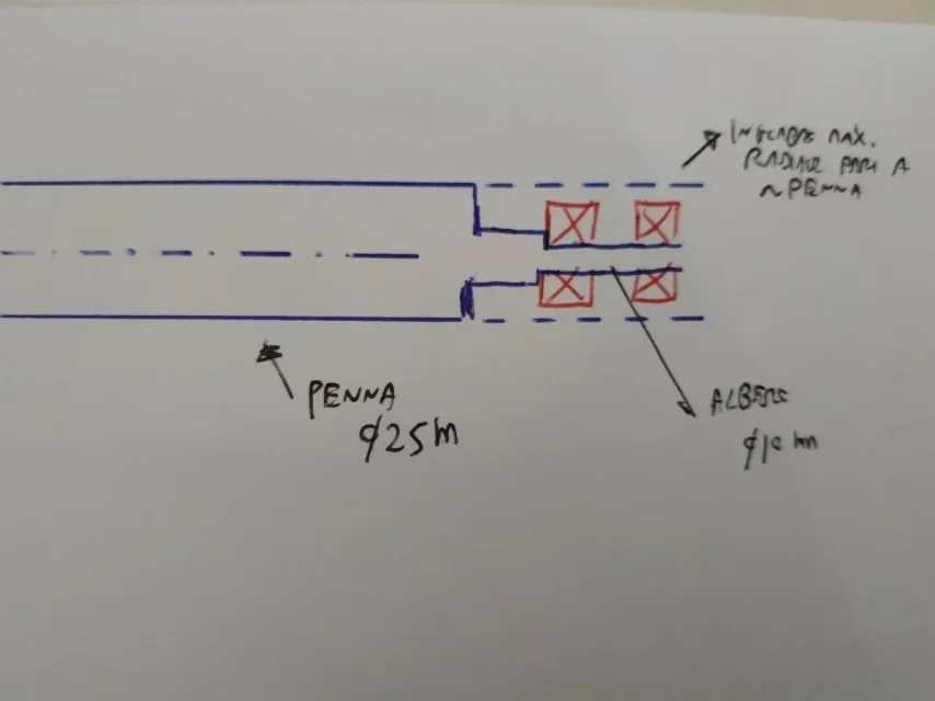
If it is the tree that breaks, I do not know the speed of rotation or the loads, but put a bronze (of those type igus or, I prefer, of those covered in ptfe) so the tree becomes bigger?

a curiosity but to define aisi304 butter.....it doesn't seem a bit drastic, I always considered it a good material as compromise to make trees since it has me it is forbidden to tempt them......I'm wrong
 
I forgot to enter the calculations,

ps teseo aisi 304 is a bit better than carpentry but mechanically cannot compete with a reclaimed or other
Meanwhile thanks to the spreadsheet I will obviously store. ....

But I wanted to point out that in the spreadsheet you put all the same elastic module values.

instead regarding aisi 304: obvious as mechanical characteristics is lower than a reclaimed or other but with a simple c40 or other it is much harder and resists corrosion, for trees according to me it is a good compromise since I can not temprare....oh correct me if I mistake because this topic interests me thank you hello
 

Forum statistics

Threads
44,997
Messages
339,767
Members
4
Latest member
ibt

Members online

No members online now.
Back
Top