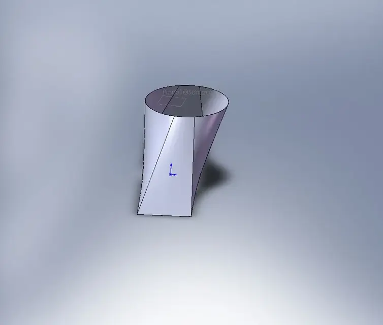
Go ahead. (I open another post because then it does not handle the attachments)now itself, same measures, but made as it should be and applying the "good rules" of the loft:
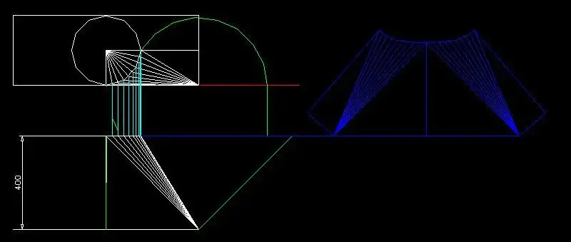
View attachment 13792. this is real, there are flat faces and rounded "pigols" to change from rectangular to round. but all "treated lines", it is understood that it is derived from a folded sheet. is no longer a unique surface but different "triangular sectors" to delimit the working areas.
of course for development there are no problems
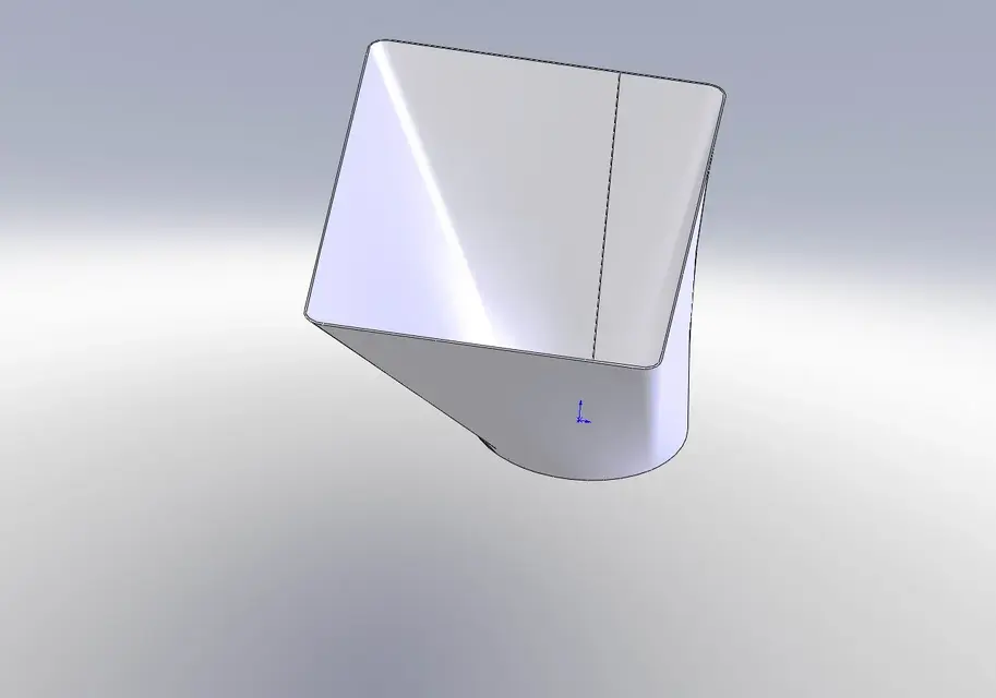
View attachment 13793. beautiful on the floor with all the edges of the rectilinear rectilinear rectilinear, as it must be, wanting (dimensions permitting) to be obtained with a net cut of cesoia (not for the other round profile). .
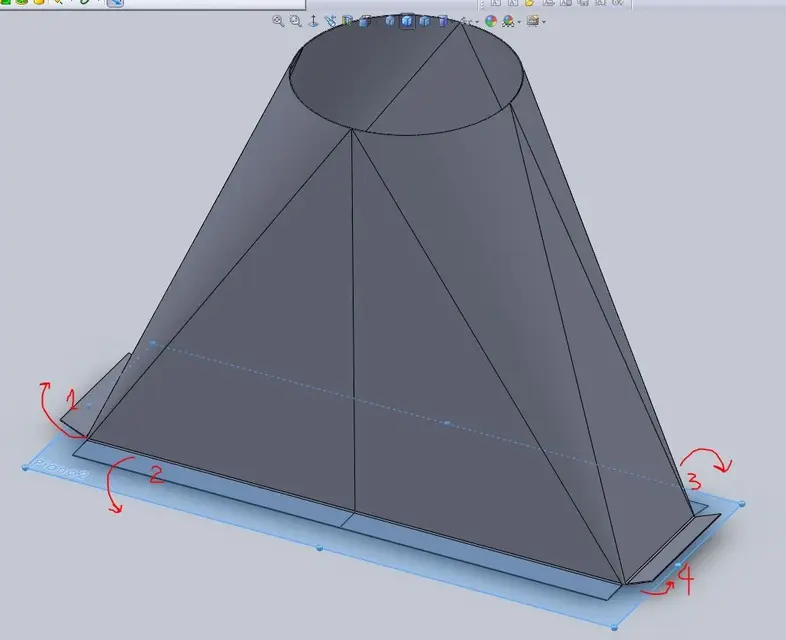
and you also put the correct lines of fold (of course you had assigned them previously in the loft property manager. Also in the example of before I put them but are ignored) so that the bending/traceler should not bang with angular calculations, just copy from the table you could quota quietly.
also of this file
View attachment 13794I've been posting the guide page, it's all explained.
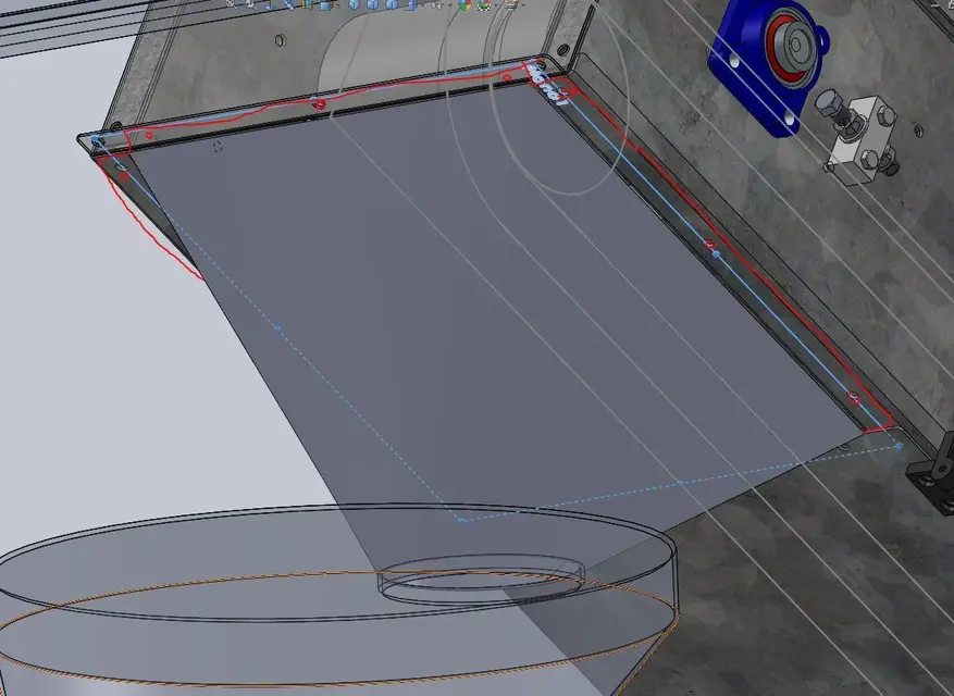
ah, and with both these models I have no problem saving in 2d for cutting the shape, both on the side and on the table.
in the end everything depends on how drawings/models, the program (which I repeat is "stupid") does what you tell him. you have to use the functions in the right way and "he" as far as it can arrive.
greetings
Marco:smile: