• This forum is the machine-generated translation of www.cad3d.it/forum1 - the Italian design community. Several terms are not translated correctly.

differences between solidworks and inventor in sheet metal environment

  • Thread starter Thread starter baleritec
  • Start date Start date

baleritec

Guest
Hello everyone,
I have always used inventor at work and having to change company, next week I will interview for a company that mainly deals with heavy carpentry and plate development. use solidworks for drawing creation.

I would need to know, from those who have experience in both programs, the substantial differences, to the professional level, between the two software for everything concerning the sheet: sheet metal and 3d modelling of pieces that will eventually be laser cutting and bending machine etc.

at first sight, in the conversion in sheet metal, the menu is not open with the various functions of sheet metal as on inventor.
therefore there is no automatic creation for example of flanges for bending, and should be drawn right?

then it is not possible to start the part as if it was already sheet, loading the various parameters?

I have difficulty understanding the "concept" of sheet in solidworks, how is it treated?

If necessary, then the examples should be loaded.

Thank you.
 
They're practically identical. both with sheet metal environment, flanges etc. both start with sheet metal or turn a solid into sheet metal. automatic developments both. treatment of the edge both.
do the tutorials and you are operational.
 
Hello everyone,
I have always used inventor at work and having to change company, next week I will interview for a company that mainly deals with heavy carpentry and plate development. use solidworks for drawing creation.

I would need to know, from those who have experience in both programs, the substantial differences, to the professional level, between the two software for everything concerning the sheet: sheet metal and 3d modelling of pieces that will eventually be laser cutting and bending machine etc.

at first sight, in the conversion in sheet metal, the menu is not open with the various functions of sheet metal as on inventor.
therefore there is no automatic creation for example of flanges for bending, and should be drawn right?

then it is not possible to start the part as if it was already sheet, loading the various parameters?

I have difficulty understanding the "concept" of sheet in solidworks, how is it treated?

If necessary, then the examples should be loaded.

Thank you.
look at some video on youtube that, even if you don't explain well, you need more than anything to understand what you can do
I have not used inventor, but the module, term that I use to mean all the dedicated functions, the sheet allows you to do a lot of things, from the calandrate sheets, to manage the type of discharges, to do the famous jealousies (see last discussion in solidworks), to do the flanges and more.
Obviously you can start directly modeling as sheet metal, which allows you to always see if there are errors in the development plan to give to laser*, but compared to other programs there is no dedicated file type and you always work in a solid environment.
there is also conversion from solid to sheet metal, very useful, to transform steps or similar.
you can export the flattened view directly from the model without going from the drawing by assigning different colors to the fold line up or down, while if you switch from the drawing you have automatic over the fold lines also the direction and degrees writings.
Certainly soolidworks is not perfect and some sin has it, but I think there is no software that satisfies 100% of the production needs. among other things is a module that is almost always improved with the advance of versions.

*when you start creating the sheet metal body you always have at the bottom of the function tree a "flattened" function that can be activated or disabled at will at any time without affecting the work already done; Moreover, in most cases if a sheet is made that cannot be developed, for example with a change of thickness or with areas that would overlap, it works with an allert.
 
I fully agree with massivonweizen, I used inventor for about 10 years and for 4 years I have been using solidworks, for what it serves me with the sheet module there are no big differences, solidworks is a little more intuitive and I have to return now to inventor I would find myself in great difficulty.
with a little tutorial you will be fully operational in a day.
 
Of course, every one of the things calls them as you want, but an account is to tell them and an account is to live them, the same difference between curled hazelnuts and the bad nutella copy. . .
 
the same difference between curling hazelnuts and the ugly nutella copy. . .
the difference makes the chiosa between the commas that if you used in your comparison sarebbbe big way: we have to do with a hazelnut, with which I mean a cream not blasoned composed however from hazelnuts, color and flavor of hazelnut, making the function of hazelnut cream

then 'this is about telling them and living them I don't understand it, what is a "extreme adventure-wild sheet" thing that could go on dmax?
 
for my personal experience changing the work I went from inventor that I used for 15 years to solidworks that I am using from three. It is true that the two modules are almost similar in the basic functions included knows the conversion from solid to sheet metal and flattening, but in my opinion the inventor module has an extra march on the greater control and number of functions (only the control of the junction of the contact lembi to inventor is in my opinion better) connected to the sheet environment. then for what you have to do you have to change slightly minded with the new commands of solidworks and therefore you will have to "reset" a moment the commands you were accustomed to but this I think is normal passing from one cad to another. However if I could want the inventor sheet module:)
 
is it possible to set the offsets of the width of the fold, directly in the modification of the "flange bottle" or the "on edge wrapping"? or in sw you have to arrange in other ways?

I attach the equivalent in inventor of what I mean. I always came back very useful.
 

Attachments

  • Screenshot (1997).webp
    Screenshot (1997).webp
    31.8 KB · Views: 29
  • Screenshot (1996).webp
    Screenshot (1996).webp
    28.1 KB · Views: 28
is it possible to set the offsets of the width of the fold, directly in the modification of the "flange bottle" or the "on edge wrapping"?
Of course, the property manager, that is the card with the setting of the works, is a part of the software that is often underestimated, but that instead contains often options that are to be analyzed and tested thoroughly because they allow to do particular things.interesting thing about the functions of solidworks, which is worth almost all, is that they integrate a sketch that can be editable back with ease; that is to create a function you can create the sketch or start directly from the function and it is indifferent because then it will be included and easily reachable back.
as you see from the video that I attach you was created a flange of the edge and then the shape is changed simply by accessing the sketch and if instead of orthogonal you had wanted to make a inclination like the design I made would have been possible and the exhaust manages it automatically1673809707467.webp
always from this video I tell you the option of the offset1673809835500.webpI repeat watch as many videos as possible
 
Last edited:
hi, the comparison between hazelnuts (commercial name) and nutella (commercial brand) with regard to me is definitely in favor of the first, with reference to what does not contain and what it contains, who was softly curious finds everything on the net. This is where I find my place: - but one account is to tell them and one account is to live them –

I press that I started using both sw and inv 9 years ago, sw I hate it though I have resumed using it currently in ut 2 years ago after a short but intense period lasted 2 years during which I used inv +topinv + d&d qs.

9 years ago with inv was love at first sight, accomplice acad, when I can buy online courses mainly for inv in addition to looking for all sorts of tutorials, for curious sw almost daily on the net, formame ( can you mention?? ) provides excellent ideas.

I will try to be as objective as possible without neglecting my judgment that will necessarily be subjective. (ii) inv > inventor, sw solidworks )

rules: with inv you follow, with sw you and you adapt or better you interpret.....

as far as I'm concerned is a kind of free hand, it lets you do as much as you want, then somehow you put a piece on it, inv forces you to reason for how it was thought, you can make variations on the theme, but then if you make clever choices you pay the consequences.

the two modules are absolutely not - practically identical - they have similar functionality/instruments, some commands are equal but are not - practically identical - it is also for the fact that from inv you can pass/convert in sheet metal a component previously shaped as solid as with sw, but only with inv you can go directly into the sheet environment, choose the thickness and the material without then having to worry about setting or correcting the sheet parameters such as fold radius.

Of course, except for having compiled (extremely simple procedure in inv) or having a sheet archive (which can be downloaded without problems from the network ) complete in its parts, a customizable table easily as the commands are simple and intuitive in addition to the fact that they can adapt according to specific equations. as regards sw the gauge tables seems to be a military secret and being based on xls sheets I do not seem to be easily configurable missing the graphic part associated with the input of numerical values. but here I'm going to the end.

sw from solid you can switch to sheet metal, inv from solid you can switch to sheet metal, you can start immediately in sheet metal environment, already said, ( having immediately available the tools for sheet) from sheet metal you can convert or revert to solid......

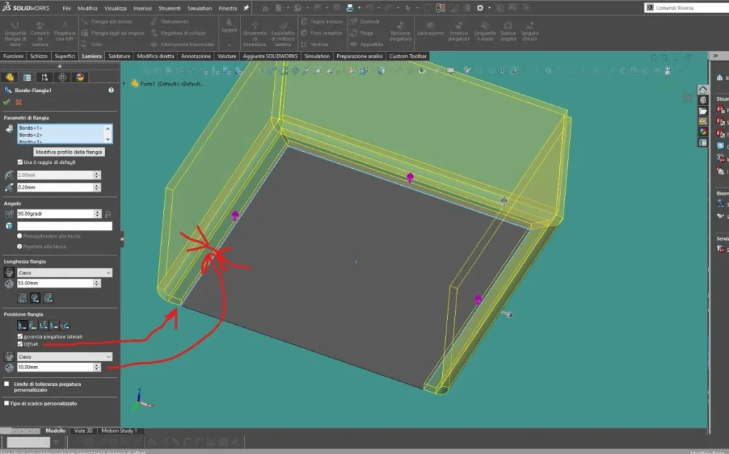
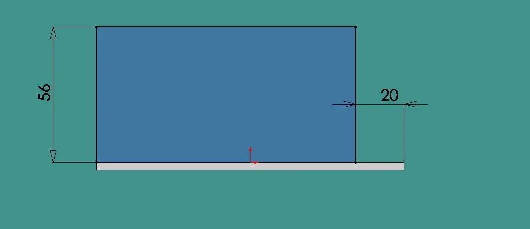
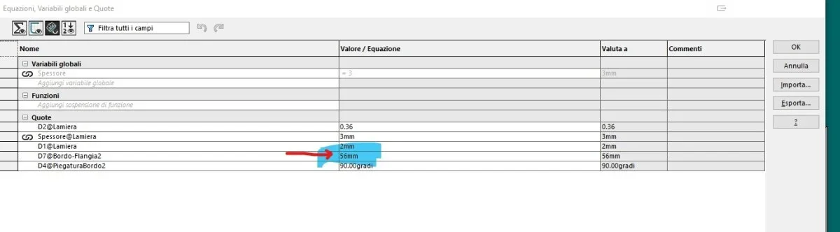
sw flange of the edge: Difficult linear modification, changing flange profile/form during creation in two steps assigning the shape of geometry as a sketch, beautiful but not always useful in the case of posthumous changes as geometric dimensions are not reported in the equations table.

if multiple flange, quini at the same time on multiple edges the change of shape must be made later for each edge.

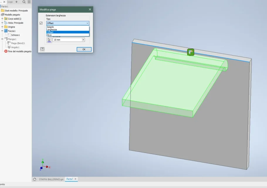
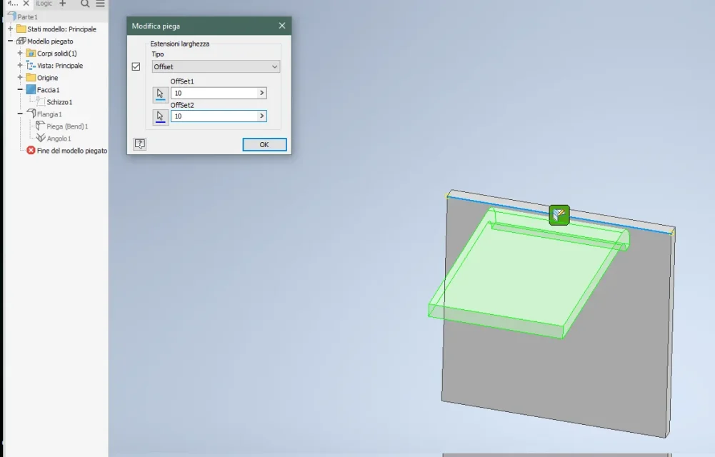
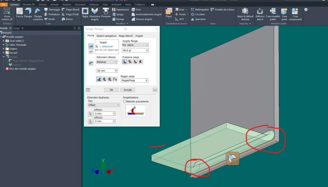
inv flange: Intuitive linear modification with real-time graphical interface, possibility for subsequent operations to maintain the parameters of the previous one, shape modification by applying sketch work.

in case of multiple flanges at the same time possibility of independent modification for each one without exiting the command.

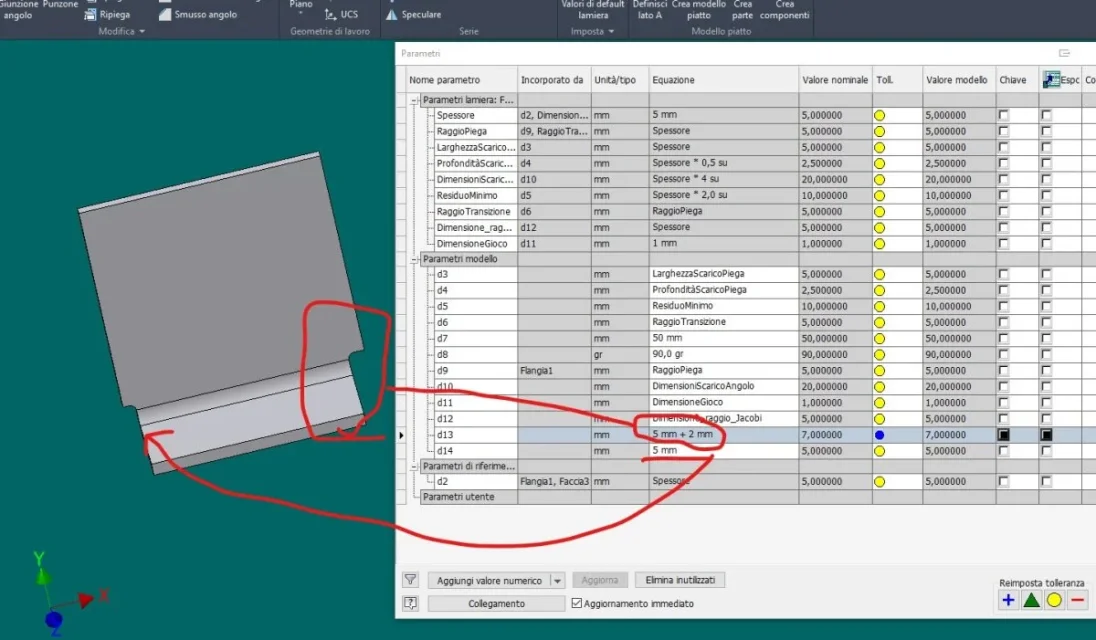
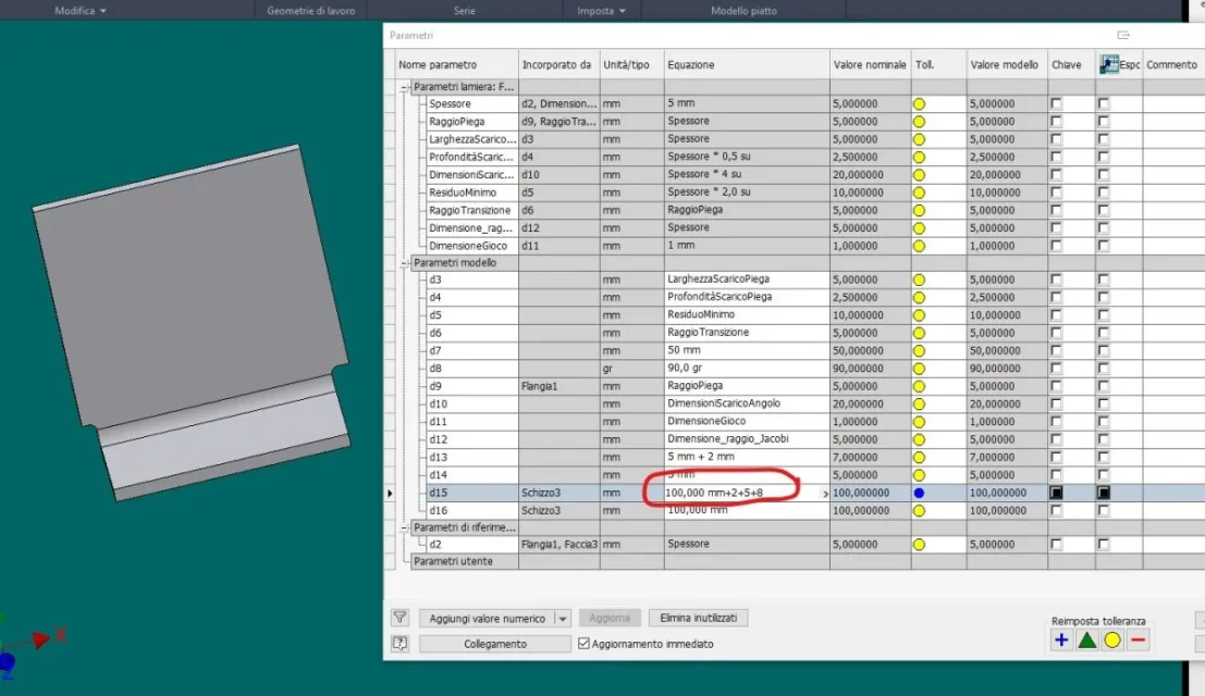
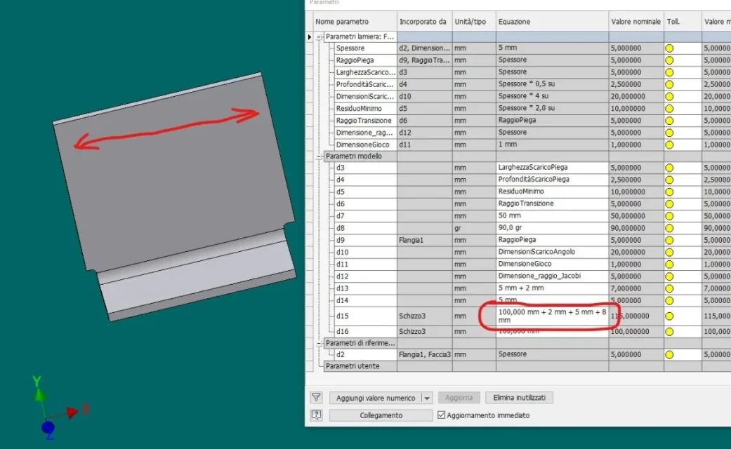
possibility to draw from list parameters, fx those that in sw are called equations for change both inv and sw

for both same position and length/extension strategy

sw edge = inv edge

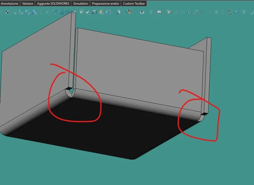
inv angle joint = sw edges > closed edge, present other processing

transversal break for diamonds, only quoteable graphics representation on the table, I also like it if you have to pay attention to the orientation in the table. I like it.

inv does not have it, but you can insert the cosmetic fold, I like more.... 
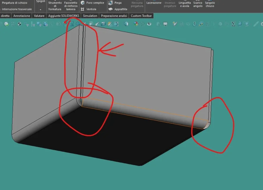
lamierainv fold (fold ): function that combines two separate faces. for me very useful.

inv fold ( fold ) : sw fold from sketch

sw staggering, interesting function that inv does not have: will it be useful??

sw reinforced handkerchief > inv nervatura but it is in model 3d

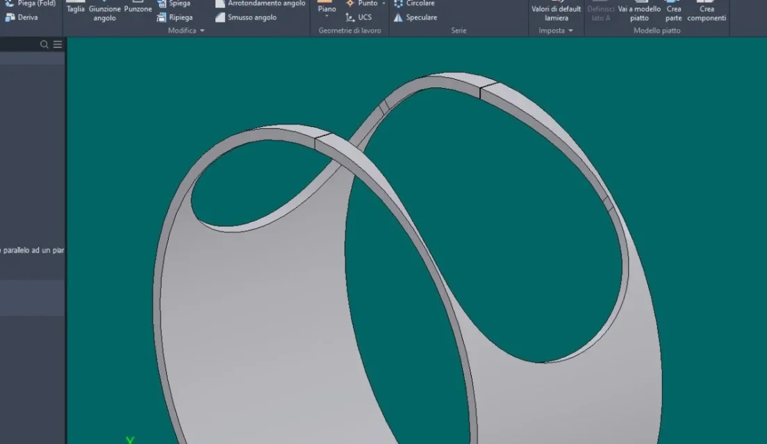
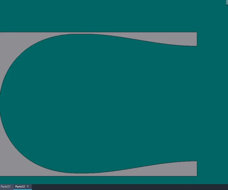
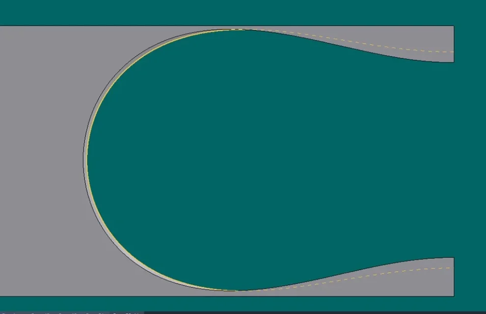
sw bending with loft > inv hopper + separation: is another story, much better than sw (see the tutorials on the net to make a hopper with sw and inv )

sw distendi + fold > inv explains + folds intuitive interface for both, I like more than inv

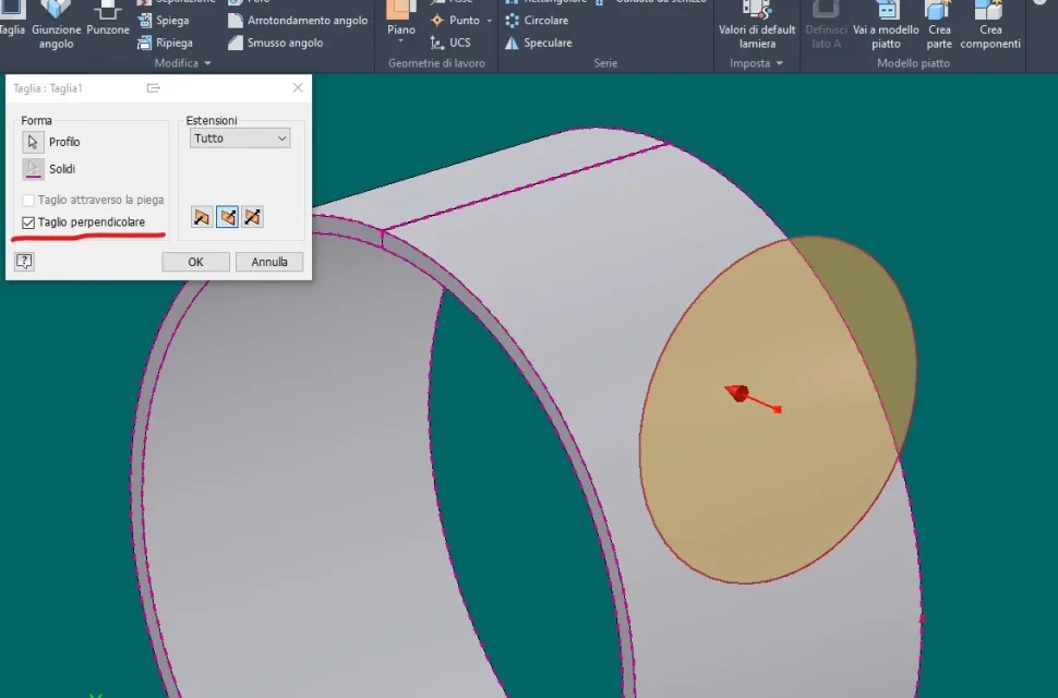
sw fan function, needs a sketch > inv punzone: all another world

archiveable punzone shapes for description and parameterizable to pleasure, for me super.

sw tongue and asola: great command, not easy to learn and manage with blocked or unlocked external references, acquired the technique will also like you.

sw toolbox vs inv design assistant, used together sheet/lamiera or solid/lamiera, solid/solid: another story, wonderful story.

the presence in addition to the 3 floors also of the relative axes are fundamental in in inv as well as the ability to enable multiple types of configurable geometric filters therefore recallable with text strings, fast keys or combination of keys that can be the same in the various working environments contrary to sw that manages only a letter or sequence of a letter + alt, shift or crtl that however should not be used in other environments.

but this exulates from the sheet metal modeling tools.

Concluding what to say? similar functions with different names, something extra on one or less on the other, it would be nice to have all those tools both in sw and inv, personally I prefer the inv sheet environment, it was also for the fact that its inv already has the sheet template.

then of course you adapt and it happens as when you learn to go cycling: you do not forget anymore and after two pedals with uncertain balance then you row straight.

the way of thinking is different, or must be, between the two and as already written:

- an account is to tell them and an account is to live them –

Thank you for the patient reading and apologize for the french.

Hi.
 
interesting thing about the functions of solidworks, which is worth almost all, is that they integrate a sketch that can be editable back with ease;
This for me is an advantage not recently.
basic but too useful for not being there.
in general for what I know and exploits the two programs (not certainly in a push way as a grace) I find and I have always found several sw commands, not only in ambient sheet, more intuitive and manageable than inv, perhaps the right term is more complete and flexible commands.
Just see the most common command in absolute "extrusion" sw gives many more possibilities and variants (extrusion offset extra or less without necessarily having to create a plan, extrusion in a direction other than perpendicular to the sketch plane.. etc.) but this is another topic.
 
a few years ago inventor did not manage what in sw is called "normal cut", does he manage it now? if I cut a sheet with an extruded cut not orthogonal to the thickness, the thickness is made orthogonal so that the cut has a coincidence of edge and no interference?
for me this function is the abc of the sheet and I was amazed that it was not present in inventor.
hi, about your statement I go about trust, you probably refer to this problem:from 2019 the problem is gone, in the images attached the options and the results, the last image refers to the problem highlighted by you
 

Attachments

  • Immagine 2023-01-16 195913.webp
    Immagine 2023-01-16 195913.webp
    33 KB · Views: 19
  • Immagine 2023-01-16 195927.webp
    Immagine 2023-01-16 195927.webp
    8.1 KB · Views: 19
  • Immagine 2023-01-16 195956.webp
    Immagine 2023-01-16 195956.webp
    46.8 KB · Views: 17
  • Immagine 2023-01-16 200151.webp
    Immagine 2023-01-16 200151.webp
    12.9 KB · Views: 23
is it possible to set the offsets of the width of the fold, directly in the modification of the "flange bottle" or the "on edge wrapping"? or in sw you have to arrange in other ways?

I attach the equivalent in inventor of what I mean. I always came back very useful.
I also reply to Massivonweizen at the same time:
hi, that feature, typical of inv with sw you forget, the offset box highlighted by massivonweizen simply turns away or falls the fold suming the + value or - to the position set in one of the 5 boxes just above.

short side folds only works after you make a flange of the edge on a edge between two existing folds, but has nothing to do with the command present in in inv

sw extrusion: Of course many are the options, alloy to the thickness then puts a piece when modeling the plates.... what is very useful is that all the values inserted are editable even without entering the change of function, directly from the equations, but only those set by that interface by inserting numerical values that are recorded/catalogated by sw.

inv extrusion: you can generate a multibody within the command by pressing the + in the bottom right without exiting the command....

the rastramazione there is in both and in both the possibility to change it independently in case of bilateral extrusion that in in inv can be managed in equal measure with a single command, which in sw imposes the input of two values. subtle function only in sw, great. sw ends closed generates a solid cable, go to understand....

ops, I forgot, inv is able to manage with the extrusion command Boolean operations (who knows rhino can understand ) with all the variables of extrusion, in practice it is an extruded cut, but much more powerful....

sw can do it with the matching command but it needs a multi-body part or part inserted inside another part, two parts to manage with the relative couplings during the insertion with everything that follows in case of change of the reciprocal position between the parts, for me it is not the maximum of simplicity....

sw the automatically generated sketches during the flange then editable: good, great, however they are not completely bound and are not editable directly in the equation board in case distances from the normal edge to that of the fold, it is necessary to make an extruded cut completely bound and quotated.

Inv, offset operation described by whaleritec, once allocated the distances in the interface, this is automatically inserted in the fx parameter table (the equivalent of sw equations) and hence editable with real-time feedback. imagine the modified operation part of a set....

it goes by itself therefore that having to insert modifications controlled by sketches it is better to take the long road and to have a greater visible control in preview acting on the parameters or on the equations rather than going for attempts going/enter changing the function.

Ultimately the numerical history, ozzac, sw performs the operations and makes the result in case of changes with arithmetic operations of the assigned odds, inv keeps the history of what you entered. sw if you do 2+2+3+5 see 12, inv if you do 2+2+3+5 see 2+2+3+5 and if you have to delete a value you know on which to act, if you then use formulas with brackets or resulting values related to other parameters .... then you open a world.
but this is another story.
Hi.
 
I'm sorry, I forgot to insert the pictures.... .
 

Attachments

  • Immagine 2023-01-16 184029.webp
    Immagine 2023-01-16 184029.webp
    29.4 KB · Views: 22
  • Immagine 2023-01-16 184111.webp
    Immagine 2023-01-16 184111.webp
    42.5 KB · Views: 21
  • Immagine 2023-01-16 184319.webp
    Immagine 2023-01-16 184319.webp
    68.7 KB · Views: 20
  • Immagine 2023-01-16 193000.webp
    Immagine 2023-01-16 193000.webp
    4.1 KB · Views: 18
  • Immagine 2023-01-16 193046.webp
    Immagine 2023-01-16 193046.webp
    16.8 KB · Views: 18
  • Immagine 2023-01-16 194110.webp
    Immagine 2023-01-16 194110.webp
    50.4 KB · Views: 16
  • Immagine 2023-01-16 194148.webp
    Immagine 2023-01-16 194148.webp
    9.1 KB · Views: 16
  • Immagine 2023-01-16 194257.webp
    Immagine 2023-01-16 194257.webp
    84.8 KB · Views: 16
  • Immagine 2023-01-16 194438.webp
    Immagine 2023-01-16 194438.webp
    81.6 KB · Views: 16
  • Immagine 2023-01-16 194506.webp
    Immagine 2023-01-16 194506.webp
    82.2 KB · Views: 19

Forum statistics

Threads
44,997
Messages
339,767
Members
4
Latest member
ibt

Members online

No members online now.
Back
Top