• This forum is the machine-generated translation of www.cad3d.it/forum1 - the Italian design community. Several terms are not translated correctly.

dimensioning helical wheel /endless screw

  • Thread starter Thread starter Vinz88
  • Start date Start date

Vinz88

Guest
boys good morning to all, having now joined the forum I thank all for the many times that I have "usufruit" of the forum to solve small problems while not being recorded.
I write today why I would need more massive help:oops:
I have the need to dimension a seamless helical/vite gearbox with the following features and unfortunately I don't know where to start.

2:1 reduction ratio (around the screw must match 1/2 gear)
brass max 35mm gear
screw of a diameter that can insert a hexagon from 22 mm as a transmission axle and stiffening system.

I hope I can fix it, thank you all.

greetings
 
a reducer of this type with ratio 1:2 I have never seen it even in a drawing. normally have minimum ratio 1:5.

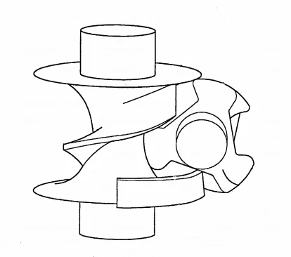
there are gearboxes similar to an endless screw reducer with ratio 1:3, but they are very particular objects, like that in figure.
G1.webpI think you have no clear ideas about it: I suggest you explain better what you have to do and we can be more helpful.
 
beyond all lacks the power or the input pair. Report 2 is impossible to achieve.
I think you should better define what you want to do.
You need two 90-degree conical gears or two skewer axes....non vfs and wheel.
 
Hello, guys, thank you for the answers and apologize if I was little accurate but I come and explain better.
My need is to rotate x elements bound on x gears coupled to a common screw.
I indicated a 1:2 ratio because the binding element should not rotate over 180° but it could actually be interesting to increase the ratio and make it more beneficial and to put mechanical stops. the power to be applied to the screw I have not yet calculated because considering that maybe they will be y screws connected to one axis will perhaps be necessary to put another element of reduction.
I hope I've been clearer. Thank you very much
 
so you do not have to size a reducer, but design a system with screw and "n" dense wheels. established that ratio 1:2 cannot be done and that you also enjoy a greater relationship, now you have to say much more if you want a hand. First of all we should know whether it is a single piece or a project for a series production: the approach to the problem is completely different. Then...
 
production would be in series.
I spoke of only one coupling because all the elements are equal and must move in the same way.
the only thing that could take is the step of the elements that have to rotate but in the end this little counts because the real transmission axis should be a smooth profile on which will insert x screw breaks in correspondence of x gears with rotating elements.
only for this reason I talked about one reducer.
Thank you.
 
In this case, it is really difficult to give you sensible advice, without knowing all the details of the project, but it would be doing the job instead of you...

do your project, and if you have doubts about one or more specific points, we are here.
 
Thanks for the support but I wanted you to recommend me even a text or guide from which to take inspiration. Thank you
 
I confirm the books niemann. I am using them at this time along with the iso6336 and din 3990 standards.
then there are the guides of khk gear that I posted several times.
you might think, once calculated (on khk I think there is the online computer)... to buy stock from them or from misfortunes or others, so drastically lower the costs and supply menades.
 

Forum statistics

Threads
44,997
Messages
339,767
Members
4
Latest member
ibt

Members online

No members online now.
Back
Top