• This forum is the machine-generated translation of www.cad3d.it/forum1 - the Italian design community. Several terms are not translated correctly.

dimensioning toothed wheels to helical teeth

  • Thread starter Thread starter Raffaele98
  • Start date Start date
I did some evidence and on the single stage you don't understand much with the numbers coming out. in the reducer two stages instead if we use u=z2/z1..... numbers greater than 1 come out completely impossible relationships because you can not go even to 20 of relationship when you have to get to 100.
so in formulas it is used as u=z1/z2.... minor numbers of 1.
who then call the or u... let's forget.
 
but I have noticed if we consider i=12 and within the formula of niemann we insert u=i for the first stage we exit u1=4,2 (so I have to consider that i=i1*i2=u=u1*u2); a result very close to what you found.
 
further, developed on the fly with freecad 0.19 with workbench fcgear, part design and workbench together with 2plus.... a work of about a quarter of an hour.. .
View attachment 64057the input shaft obtained from full and carved the elica of the gear. Like this tree down here.View attachment 64059pinion second stage obtained from full integral with pinion.
the two wheels of the two states calettate with tongue on the respective trees.
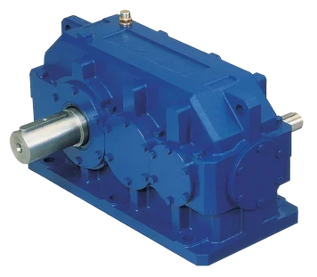
the external volume is that of the above mentioned trade reduttor and actually we are in it well, so it means that the internal subdivision logic of the reduction ratio with the first stage i=4 and the second stage i=3 worked correctly.
View attachment 64058being that this reducer to catalog has been definitely designed with old regulations, it goes from itself that the gear bands are deducted from, according to always the criterion used at the time, of a 10-20mm so as to have a little more useful space as it would seem to be there in catalog.
I also wanted to ask you by making the pinion directly on the tree, in my case where I have a dp of 130, isn't it exaggerated?
 
but I have noticed if we consider i=12 and within the formula of niemann we insert u=i for the first stage we exit u1=4,2 (so I have to consider that i=i1*i2=u=u1*u2); a result very close to what you found.
Don't give me "she" otherwise I'll see who you're talking to a
with low reports seems to work....but what you have to try is the three stages ... that if you use a ratio greater than one ... you get on the second stage type 45 and 2 on the first. This makes me deduce that we have to insert the values below one....and to be such if a reducer reduces 6 ....we will have to write 1/6.
 
I also wanted to ask you by making the pinion directly on the tree, in my case where I have a dp of 130, isn't it exaggerated?
What do you mean he's exaggerated? You have to look at the proportions. if you have a gear of a certain diameter you have to try to calculate even torsion alone with factor 6 as it comes out of diameter. If the difference is so much it is best to throw the gear on the input tree, otherwise if it is not so big you can safely do integral.
 
I made a maximum sizing and determined by means of von mises the minimum diameter and comes out of about 30 mm, while the primitive diameter is 130 mm if I use 21 teeth and 105 if I use 17
 
I made a maximum sizing and determined by means of von mises the minimum diameter and comes out of about 30 mm, while the primitive diameter is 130 mm if I use 21 teeth and 105 if I use 17
If you maintain these values means that you will have the input shaft of 30 mm... then you have diameter for bearings at least around 40.... seen that you will also pass to seal. ...magari ghiera etc. then you will climb to about 50 mm in diameter for the jug of the wheel with tongue. I would say that it could be in both cases the cobbling on a tree. If you make hardened and rectified concrete wheels you may consider making the 42crmo4 stainless steel shafts so that not the traits. the wheels you can decide to treat only the teeth and protect the rest, so optimize a bit the costs.
 
If you maintain these values means that you will have the input shaft of 30 mm... then you have diameter for bearings at least around 40.... seen that you will also pass to seal. ...magari ghiera etc. then you will climb to about 50 mm in diameter for the jug of the wheel with tongue. I would say that it could be in both cases the cobbling on a tree. If you make hardened and rectified concrete wheels you may consider making the 42crmo4 stainless steel shafts so that not the traits. the wheels you can decide to treat only the teeth and protect the rest, so optimize a bit the costs.
In fact, the dimensioning I made it in the area of pickling of the pinion, which from the graphics of the moment (fleshing and torque) was the most stressed. as static security factor I used 1.5.
 
Something's not coming back.
We start from 100kw to 1400rpm.
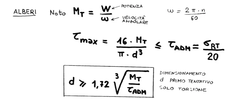
angle speed [math]\omega=2•π•n/60=146.5 rad/s[/math]from which the torque moment:[imath]mt=\frac{w}{\omega}=682.5 nm[/imath]therefore applying the formulas of first sizing only torsion, with a 42crmo4 reclaimed we have:
Screenshot_20211216_213936.webp
Screenshot_20211216_220951.webphypothesizes the admissible voltage [math]\tau=\frac{1100}{20}=55mpa[/math]I draw the diameter that is approximately or greater than 40mm.
This is what will happen in the tree outside the gearbox where there is the headquarter for the connection by means of the motor.
then you will put 45 the shaft bar....50 the bearing....55 the bearing bar and 60 the diameter of gushing.
After this sizing you will build the design of the shaft... the bearings. ...check the bearings.... so only now you have the true length. only now you can do atactic verification with internal stresses and subsequently evaluate carvings, concentration of efforts and fatigue.
 
if you make it simple....1100mpa is the break...moltiplichi 0.8 and get the yield....moltiplichi for 0,58 get the tau and divide for a coefficient at least 2....you get an admissible 250mpa tau that leads to at least 24 mm of tree only torsione. ..His tongue is 5.4 mm deep that sums to 24 do 30mm.
then pinned tree 35....seat 40...battuta bearing 45... and becomes 50 where the gear falls.
 
@meccanicamg I, on the other hand, did a shaft sketch by choosing the distance between pinion and bearings and calculated the reactions on the bearings and I did the cutting diagrams and moment according to the values I dimensioned the shaft statically with vm.
is it, therefore, wrong as a procedure?
 
if you make it simple....1100mpa is the break...moltiplichi 0.8 and get the yield....moltiplichi for 0,58 get the tau and divide for a coefficient at least 2....you get an admissible 250mpa tau that leads to at least 24 mm of tree only torsione. ..His tongue is 5.4 mm deep that sums to 24 do 30mm.
then pinned tree 35....seat 40...battuta bearing 45... and becomes 50 where the gear falls.
excuse ignorance, can't I mount the bearing on the diameter of 35 and put it in line on the diameter of 40 and caletto the pinion on the tree of 45?
 
Something's not coming back.
We start from 100kw to 1400rpm.
angle speed [math]\omega=2•π•n/60=146.5 rad/s[/math]from which the torque moment:[imath]mt=\frac{w}{\omega}=682.5 nm[/imath]therefore applying the formulas of first sizing only torsion, with a 42crmo4 reclaimed we have:
View attachment 64107
View attachment 64108hypothesizes the admissible voltage [math]\tau=\frac{1100}{20}=55mpa[/math]I draw the diameter that is approximately or greater than 40mm.
This is what will happen in the tree outside the gearbox where there is the headquarter for the connection by means of the motor.
then you will put 45 the shaft bar....50 the bearing....55 the bearing bar and 60 the diameter of gushing.
After this sizing you will build the design of the shaft... the bearings. ...check the bearings.... so only now you have the true length. only now you can do atactic verification with internal stresses and subsequently evaluate carvings, concentration of efforts and fatigue.
a last thing to us the admissible tau has said that the safety coefficient is calculated as a tau dinervamento fracto the safety coefficient, with tau dinervamento equal to the root fract of 3
 
excuse ignorance, can't I mount the bearing on the diameter of 35 and put it in line on the diameter of 40 and caletto the pinion on the tree of 45?
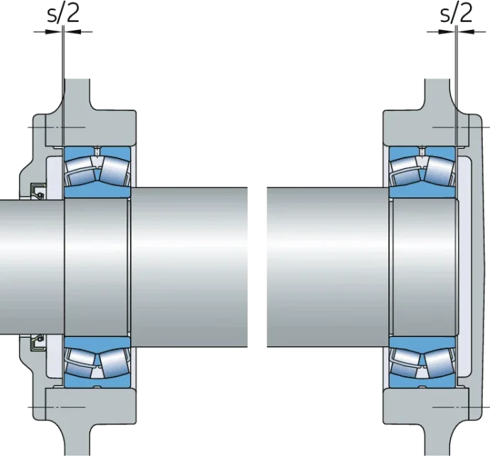
If you place a mounting scheme we can see what and how. especially the type of bearings, if you make a floating system or not.
 
a last thing to us the admissible tau has said that the safety coefficient is calculated as a tau dinervamento fracto the safety coefficient, with tau dinervamento equal to the root fract of 3
0.58*rs/k.... certainly though on applications where you twist, bending, cutting, reverse motion, not uniformity of motion, it does not especially with dimensioning stay low.

dimensional can do it, as I said in various posts, with empirical formulas, charts, randomly etc. then it is the verification that must be strict, to norm etc.

your flexing and twisting tree is valid with your accounts, if I put 0.5 mm radius on the shoulders, the tab seat and other things that generate carving, if solicited to fatigue give insufficient and then after a number of cycles will break the tree.

Moreover if you have a big difference between shaft diameter and wheel, being helical....you have effects of slipping to s.
 
Yes but it's just to make you understand @raffaele98 from where that value comes, that is, you are talking about the same thing.
Of course, I'm the same.
my "battuta" is because in reality 0.577 or 0.58 does not change anything in reality because there are then large coefficients at stake.
I certainly did not mean that your punctuation was useless, indeed ,
 
skf is a good bearing manufacturer and has many notes, explanations and images.

I'll take you back here under a few frames to show you the steps and the jokes.
Floating mounting0901d19680600c83-1703-0012---17000-w_tcm_12-292197.pngthis is the simplest and cheapest assembly system. bearings of various types are used (ball radials, adjustable barrel radials etc). is a system that offers radial reactions from both bearings and an axial reaction to the right or left depending on the spins of the loads and/or the direction of rotation. the diameter of the seat seal of the bearing seat would be well different to facilitate assembly.

as you see the trees coming out of the case have a further reduction of diameter to offer a pin to the joints that will be mounted.
1639768561612.png
 

Forum statistics

Threads
44,997
Messages
339,767
Members
4
Latest member
ibt

Members online

No members online now.
Back
Top