• This forum is the machine-generated translation of www.cad3d.it/forum1 - the Italian design community. Several terms are not translated correctly.

dimensioning toothed wheels to helical teeth

  • Thread starter Thread starter Raffaele98
  • Start date Start date
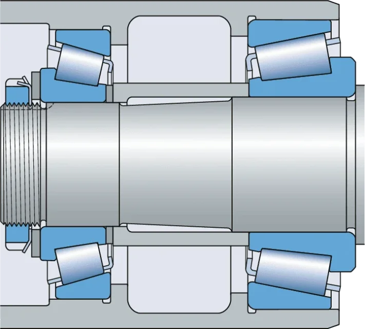
mounting to or hyperstatic0901d196805ecdd2-1702-0020---17000-w_tcm_12-292193.webptwo conical roller bearings are used to or from the axis. this system is more rigid and suitable than the precise application. as you see we have spacers that make the axial shaved preload and the wreath keeps to pack everything concerning the inner rings.
this system adds a step and then an extra jump with its shouldering compared to the method described above (flapping).

then there are many other intermediate solutions that you explain also qui.

then there are very poor solutions, which are also made at an industrial level, where the step of the external shaft is eliminated, the diameter of the seal is raised and leaves all a single diameter including the bearing. you avoid as much as possible, you use some seegers and many spacers. However, it is necessary to be careful and, in any case, solutions adopted in the floating mode. However, they are solutions to save and optimize but it is necessary to proceed with caution and know well the behaviour of the load and where the reducer goes.
 
It would be enough to look at how a two-stage industrial reducer is built to understand that there are more steps on the "pignone" trees.
c2_pdiric.giffor example this reducer does not have the barks on the input/output trees.
 
If you place a mounting scheme we can see what and how. especially the type of bearings, if you make a floating system or not.
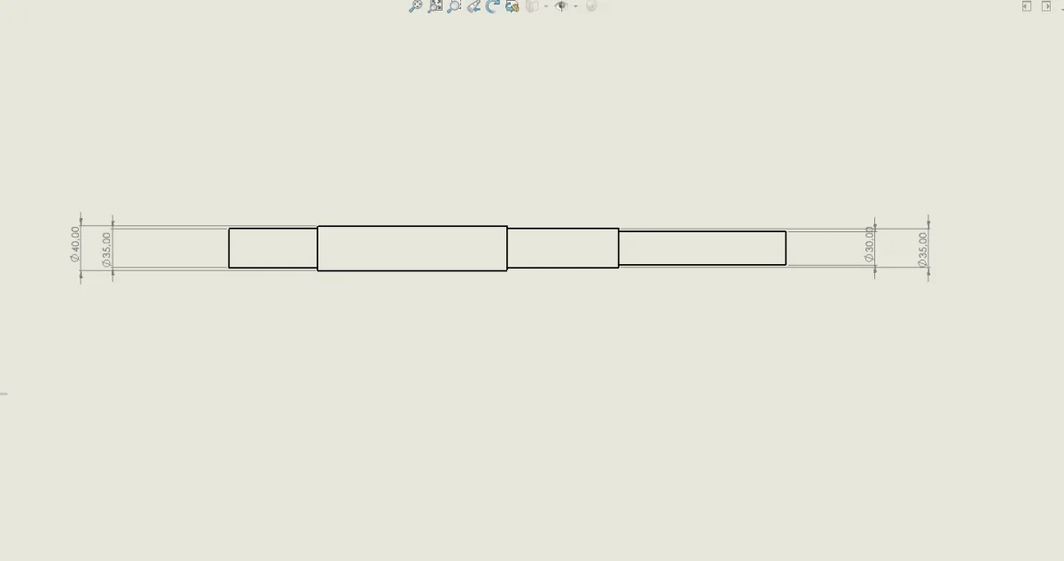
This, of course, is how I thought I was doing the tree. 30 mm is the diameter out of the reducer for connection with the motor, 35 shaft bar and bearing, finally, 40 is the diameter for pinion tapping and bearing bar.Screenshot (83).webp
 
could go: how do you think you block the pinion?
do not forget to draw the axis of symmetry.

If you predict a tab, the diameter of 40 for the pinion may not be enough
 
30 mm is the diameter out of the reducer for connection with the motor, 35 shaft bar and bearing, finally, 40 is the diameter for pinion tapping and bearing bar.
to me that 40 leaves me puzzled because as you see from the scheme the larger diameter is generally not engaged and is the starting diameter of the commercial traphylase; perhaps with a pattern, as written by mechanicsmg, would be clearer.
 
could go: how do you think you block the pinion?
do not forget to draw the axis of symmetry.

If you predict a tab, the diameter of 40 for the pinion may not be enough
by tab, assuming distances between bearings and pinions and statically dimensionalizing with vm, I get out a diameter of 28, the quarry of the tab for a shaft of diameter equal to 40 mm is 5mm. So I think that statically should resist, now I should see fatigue.
 
to me that 40 leaves me puzzled because as you see from the scheme the larger diameter is generally not engaged and is the starting diameter of the commercial traphylase; perhaps with a pattern, as written by mechanicsmg, would be clearer.
So is it better to start from a greater diameter than the thread and leave it free?
 
to me that 40 leaves me puzzled because as you see from the scheme the larger diameter is generally not engaged and is the starting diameter of the commercial traphylase; perhaps with a pattern, as written by mechanicsmg, would be clearer.
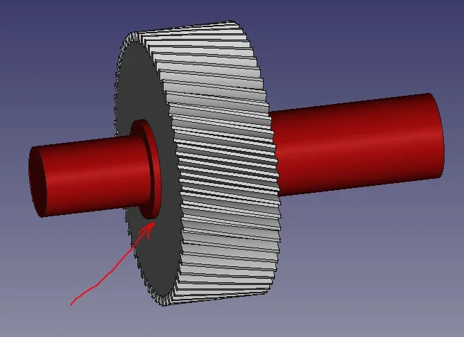
if you cast a toothed wheel that has hole and seat for tab on a tree, this tree somehow has to have an axial locking match on one side and something that on the other pushes against. I don't think you want to do the whole axial package just with the bearings.
then the shaft will have to have a more diameter bar than the wheel's jacking, not to let it move.1639821275722.webp
 
All right, thank you. I was reviewing the formula you posted for the admissible tau, 1/20 could you explain to me what it was due to?
 
This, of course, is how I thought I was doing the tree. 30 mm is the diameter out of the reducer for connection with the motor, 35 shaft bar and bearing, finally, 40 is the diameter for pinion tapping and bearing bar.View attachment 64129
first you need to understand what material you used. If you use a steel tied in bar, for example a 40crmo4 or a 39nicrmo3 that are those that are used to make the gear shafts with good fatigue resistance, it is essential to clarify and focus that they will not be tempered but you will use the bar that is pre-bonified on the market. so you have to go look on a sheet of steel manufacturers what they give you as values.

in my previous posts I put the table for the 42crmo4 and indicatively on a 50mm essay about give you tensile breakage 900-1100mpa. being a ductile steel, if you can not have the rp0.2 or rs load should be hypothesized and therefore...from the theory we know that it is worth about 80% of the breaking load. to know just take some steels and see the values reported.

therefore we start from a maximum yield load rs=880mpa and minimum 720mpa. so let's take to rest a half way rs,adm=750mpa.

Ductile steel, from the theory is expected a safety coefficient greater than 1.5 and since the application can also be challenging (we assume that the reducer goes into the steel field) I would say that at least one safety factor 2-3 we have to put it. Let us remember that factor 3 is low if we go to evaluate the fatigue then, that is why normally to shoot for the dimensionals factors 6 or 10.

without knowing that bearings will go to put and without knowing that gears I put on it I can only immediately establish the outer diameter of tree.

we said that they enter 100kw to 1400rpm which are about 680nm (by memory).
permissible voltage = 0.58*rs/k=145mpa if we use k=3.
tension in a round due to twist using the formulas you have (I doubt that you have taught some niemann formulas for pure twist) = 16*mt/(3.14*d^3) --> equaling the embroidery tensions d>31mm.

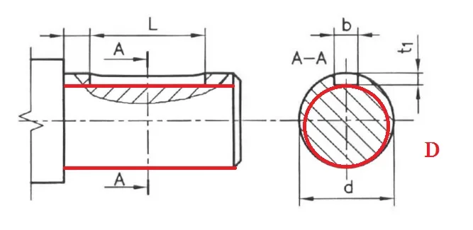
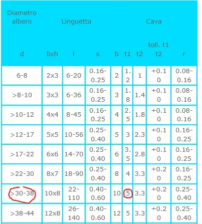
but this is a smooth tree... without tongue and you calculated the red one of d.1639822129857.webpat this point you have to put, looking at the table the value of t1 that for a tree from d=31 is worth t1=5.1639822202373.webptherefore your tree outside, where there is only twist (with the due assumptions) is at least 36mm.

then now depending on the mounting scheme you will find to grow the diameters. but do not believe that they are increased only to make jokes... there are also tensions that rise.
 
first you need to understand what material you used. If you use a steel tied in bar, for example a 40crmo4 or a 39nicrmo3 that are those that are used to make the gear shafts with good fatigue resistance, it is essential to clarify and focus that they will not be tempered but you will use the bar that is pre-bonified on the market. so you have to go look on a sheet of steel manufacturers what they give you as values.

in my previous posts I put the table for the 42crmo4 and indicatively on a 50mm essay about give you tensile breakage 900-1100mpa. being a ductile steel, if you can not have the rp0.2 or rs load should be hypothesized and therefore...from the theory we know that it is worth about 80% of the breaking load. to know just take some steels and see the values reported.

therefore we start from a maximum yield load rs=880mpa and minimum 720mpa. so let's take to rest a half way rs,adm=750mpa.

Ductile steel, from the theory is expected a safety coefficient greater than 1.5 and since the application can also be challenging (we assume that the reducer goes into the steel field) I would say that at least one safety factor 2-3 we have to put it. Let us remember that factor 3 is low if we go to evaluate the fatigue then, that is why normally to shoot for the dimensionals factors 6 or 10.

without knowing that bearings will go to put and without knowing that gears I put on it I can only immediately establish the outer diameter of tree.

we said that they enter 100kw to 1400rpm which are about 680nm (by memory).
permissible voltage = 0.58*rs/k=145mpa if we use k=3.
tension in a round due to twist using the formulas you have (I doubt that you have taught some niemann formulas for pure twist) = 16*mt/(3.14*d^3) --> equaling the embroidery tensions d>31mm.

but this is a smooth tree... without tongue and you calculated the red one of d.View attachment 64133at this point you have to put, looking at the table the value of t1 that for a tree from d=31 is worth t1=5.View attachment 64134therefore your tree outside, where there is only twist (with the due assumptions) is at least 36mm.

then now depending on the mounting scheme you will find to grow the diameters. but do not believe that they are increased only to make jokes... there are also tensions that rise.
I understood thanks, what I couldn't understand was because using the torsion formula that you placed you find me a greater value than the diameter I echoed with vm, where I also consider the bending, I had imagined that the problem was the safety coefficient used, but I couldn't understand what was used.
 
All right, thank you. I was reviewing the formula you posted for the admissible tau, 1/20 could you explain to me what it was due to?
is an empirical formula due to a series of geometric singularities that can give problems. the tree that comes out as a reducer has mainly two "defects" for fatigue:

- the seat of the tab and therefore the concentration of efforts that can break the material as in the figure
42168-d15c007f1d0dacfe0dd1ec979c6ce6af.jpg
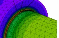
- the connection radius between shaft and shoulder1639822607374.webpabout this problem, I suggest you look This is what discussion where a colleague of yours had a nice bunch of fems on trees with these types of problems and had to analyze the overlap of the effects of can stresses and "defects" on the trees.

if you block also the bearing with a wreath that has the safety rosette you have in the same area also a frigate that reduces the big diameter and also a thread that leaves in that area. being there a wreck traction in that area, which is not part of the actions generated by external constraints/loads but that the tree feels everything creating tensions of traction.
0901d196804a7cd1-1311-0036---14266-w_tcm_12-270031.png
that is why the classic factor k=1.5 on a ductile then becomes a 6...10 on the yield and a 20 on the breaking load to refer to the octaedral tension.

clearly it would be good that they explained these things to you in lesson, because then in the world of work there are a series of dynamics that unfortunately do not always allow you to experiment and make training by hand....you know when the trees break are pains, money, figures etc.
 
is an empirical formula due to a series of geometric singularities that can give problems. the tree that comes out as a reducer has mainly two "defects" for fatigue:

- the seat of the tab and therefore the concentration of efforts that can break the material as in the figure
42168-d15c007f1d0dacfe0dd1ec979c6ce6af.jpg
- the connection radius between shaft and shoulderView attachment 64137about this problem, I suggest you look This is what discussion where a colleague of yours had a nice bunch of fems on trees with these types of problems and had to analyze the overlap of the effects of can stresses and "defects" on the trees.

if you block also the bearing with a wreath that has the safety rosette you have in the same area also a frigate that reduces the big diameter and also a thread that leaves in that area. being there a wreck traction in that area, which is not part of the actions generated by external constraints/loads but that the tree feels everything creating tensions of traction.
0901d196804a7cd1-1311-0036---14266-w_tcm_12-270031.png
that is why the classic factor k=1.5 on a ductile then becomes a 6...10 on the yield and a 20 on the breaking load to refer to the octaedral tension.

clearly it would be good that they explained these things to you in lesson, because then in the world of work there are a series of dynamics that unfortunately do not always allow you to experiment and make training by hand....you know when the trees break are pains, money, figures etc.
It's better not to talk about what they explain in class and then what they ask for in writing. . .
 
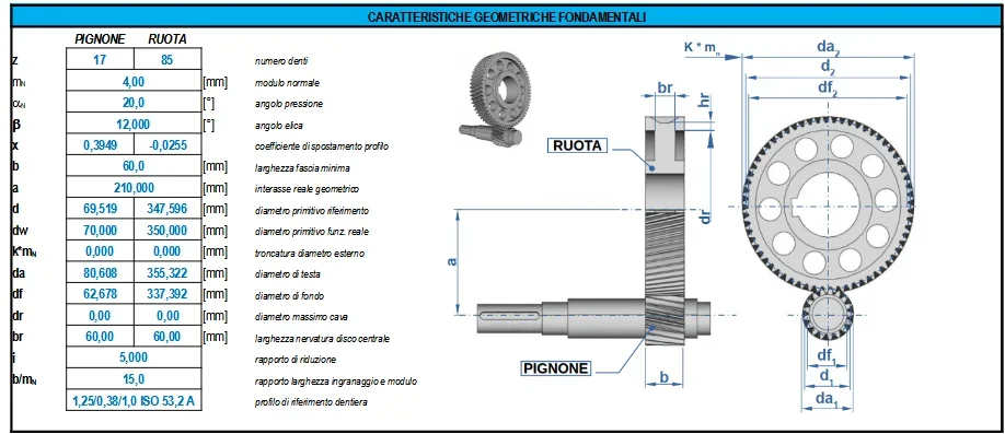
just to get some indications of forces that I've...now I don't remember when you did the first stage of the reducer, but we don't go so far... let's do the =5.1639823127261.webpso we have 60mm band, we leave 20mm per part, we put the bearings that will be about 30 wide and therefore we have symmetrically from center 55-60mm.

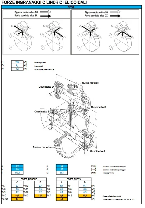
calculate the 3 forces at the point of contact and obtain the reactions on the tree (valid only for the entry, because the second tree will have the overlap of the forces of the two stages) we will have:1639823291763.webpLet's throw it there coarsely without making the accounts rigorously. we are talking about about 13kn reaction to the radial bearing multiplied by 60mm makes a flender moment from 780000nmm.
we have therefore in the center on a diameter 50mm a sigma of vm due to the bending and torsion of 85mpa. we certainly neglected something else....like cutting.
statically, you're overwhelmed, but if you put the carvings around that space, which at least have a kt=2, you get a 160/200mpa voltage that if you have something alternating like a motorcycle, it gives you a finished cycle.
 
So if I use break sigma/20 in vm when I dimension statically how do I write admissible sigma? Also as safety coefficient I must always use 20 right? I apologize for all these questions
 
So if I use break sigma/20 in vm when I dimension statically how do I write admissible sigma? Also as safety coefficient I must always use 20 right? I apologize for all these questions
when you make the sizing torsion only, the tau and not the admissible sigma will be calculated as about rm/20. already because 0.58*rm is about equal to rm/2 is practically the tau twist to break. then you have a coefficient 10 that you can indicate how k (maybe you can do even only 6) that you put to the denominator and indicates a static and dynamic global security factor. written a little more scientifically becomes:[math]\tau_{adm}=\frac{0.577*rm}{k}; \frac{1}{\sqrt{3}}=0.577; k=6...10[/math]but this does not hit anything with von mises.

remember: dimensional means hypothesize, determine, impose numbers. checking instead means checking, analyzing, knowing exactly. different formulas are used.
 
when you make the sizing torsion only, the tau and not the admissible sigma will be calculated as about rm/20. already because 0.58*rm is about equal to rm/2 is practically the tau twist to break. then you have a coefficient 10 that you can indicate how k (maybe you can do even only 6) you put to the denominator. written a little more scientifically becomes:[math]\tau_{adm}=\frac{0.577*rm}{k}; \frac{1}{\sqrt{3}}=0.577; k=6...10[/math]but this does not hit anything with von mises.

remember: dimensional means hypothesize, determine, impose numbers. checking instead means checking, analyzing, knowing exactly. different formulas are used.
sisi lo sò, was right to have a correlation between the two results
 

Forum statistics

Threads
44,997
Messages
339,767
Members
4
Latest member
ibt

Members online

No members online now.
Back
Top