michelefiorentin
Guest
dear caders,
in the modelling of a small plane for educational reasons we are encapsulated in this part here in generative sheetmetal (1mm thick) :
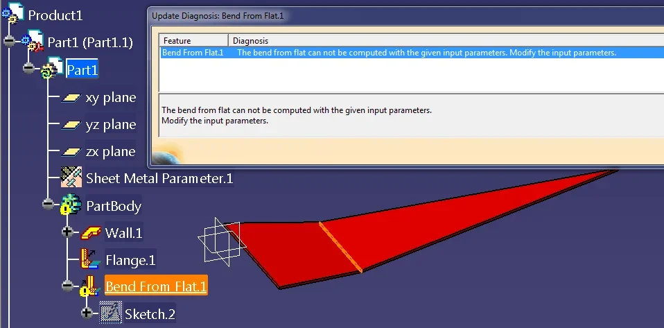
![PDF Architect - [cri_cri_planos - 00037]_2013-07-02_10-55-29.webp PDF Architect - [cri_cri_planos - 00037]_2013-07-02_10-55-29.webp](https://3dcad.news/community/data/attachments/28/28850-fffff9c6d5452864eb7dfcc9f06e843f.jpg?hash=KWtFsKxBp1) I tried first the "bruto" method of double bending in sequence with this result:
I tried first the "bruto" method of double bending in sequence with this result:
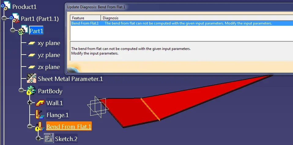
 then I went to realize it but the only way is to bend it perpendicularly to the long side, then create the walls on the sides. where there is the elbow on the long side I remain 2 openings and also irregularities
![CATIA V5 - [Product1]_2013-07-03_07-52-22.webp CATIA V5 - [Product1]_2013-07-03_07-52-22.webp](https://3dcad.news/community/data/attachments/28/28853-371dee4d6f3d7c01bbfd9d66011b3518.jpg?hash=v6jsQAVTC4) Do you have any advice? I saw some examples of sheet metal in double curvature. how would you solve the problem?
Do you have any advice? I saw some examples of sheet metal in double curvature. how would you solve the problem?
greetings and thanks
in the modelling of a small plane for educational reasons we are encapsulated in this part here in generative sheetmetal (1mm thick) :
![PDF Architect - [cri_cri_planos - 00037]_2013-07-02_10-55-29.webp PDF Architect - [cri_cri_planos - 00037]_2013-07-02_10-55-29.webp](https://3dcad.news/community/data/attachments/28/28850-fffff9c6d5452864eb7dfcc9f06e843f.jpg?hash=KWtFsKxBp1) I tried first the "bruto" method of double bending in sequence with this result:
I tried first the "bruto" method of double bending in sequence with this result: then I went to realize it but the only way is to bend it perpendicularly to the long side, then create the walls on the sides. where there is the elbow on the long side I remain 2 openings and also irregularities
![CATIA V5 - [Product1]_2013-07-03_07-52-22.webp CATIA V5 - [Product1]_2013-07-03_07-52-22.webp](https://3dcad.news/community/data/attachments/28/28853-371dee4d6f3d7c01bbfd9d66011b3518.jpg?hash=v6jsQAVTC4) Do you have any advice? I saw some examples of sheet metal in double curvature. how would you solve the problem?
Do you have any advice? I saw some examples of sheet metal in double curvature. how would you solve the problem?greetings and thanks


![CATIA V5 - [Product1]_2013-07-08_08-19-40.webp CATIA V5 - [Product1]_2013-07-08_08-19-40.webp](https://3dcad.news/community/data/attachments/28/28899-f98f112c498d0789c572735d02fffc19.jpg?hash=-3BajybMJ_)
![CATIA V5 - [pezzo forum piegato.CATPart]_2013-07-11_18-33-55.webp CATIA V5 - [pezzo forum piegato.CATPart]_2013-07-11_18-33-55.webp](https://3dcad.news/community/data/attachments/28/28950-6b3e2c02bca66ef4880a5f93af38f726.jpg?hash=9ZPxV5ir9-)
![CATIA V5 - [pezzo forum piegato.CATPart]_2013-07-11_18-33-42.webp CATIA V5 - [pezzo forum piegato.CATPart]_2013-07-11_18-33-42.webp](https://3dcad.news/community/data/attachments/28/28951-cf7369d3a65c99433517e1f0346dcfc3.jpg?hash=-2pEYZVF3H)