Mattia1997
Guest
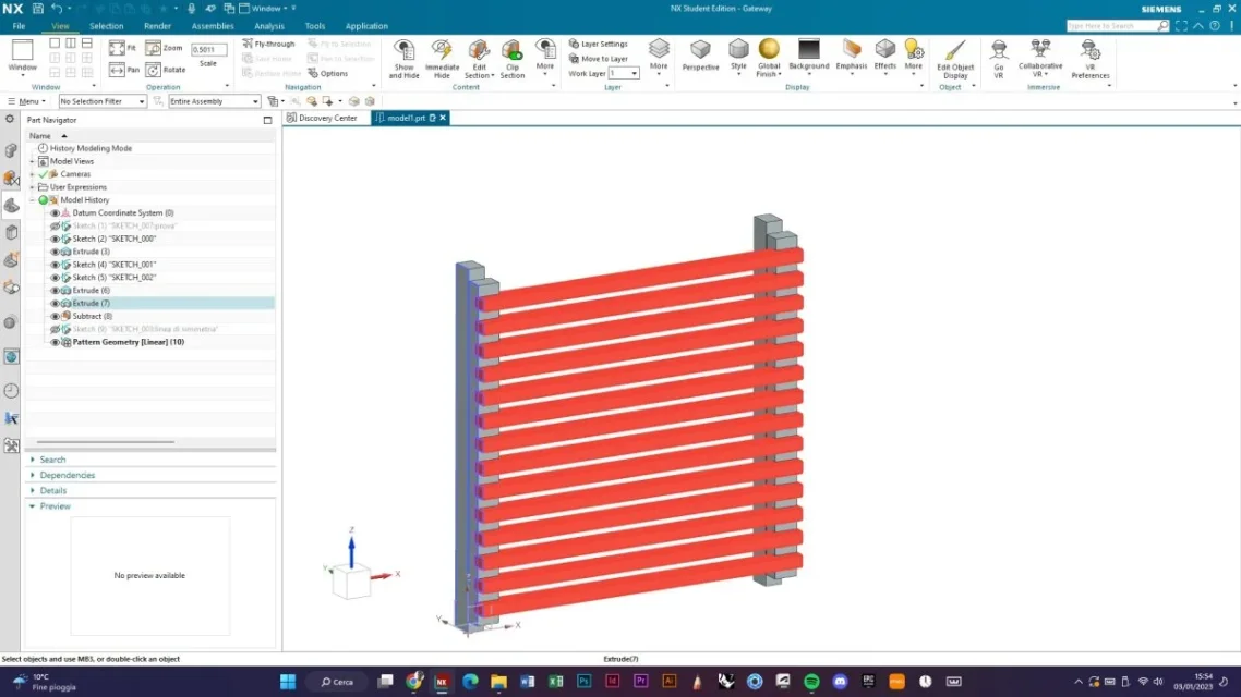
Good morning, I'm using siemens nx for design. However I have a problem and ask for advice to this community. I should make this object parametric, which I leave in the photo, to make you understand better. In particular, I would need that when the length of the strips (red) were increased, the structures (grey) were created automatically. the "grille" I would like to be editable in length (strengthening the red strips) and in height (increasing the height of the grid and therefore increasing the number of red strips, not the thickness). all in a associative way.
I would need the formula or equation but not very practical, do you have advice or possibly know how to make the formula? for any I leave the mail mattiama97chiocciolahotmailpuntocom. I hope to have been clear even if I understand the difficulty.
Morning
I would need the formula or equation but not very practical, do you have advice or possibly know how to make the formula? for any I leave the mail mattiama97chiocciolahotmailpuntocom. I hope to have been clear even if I understand the difficulty.
Morning
Attachments
Last edited by a moderator:
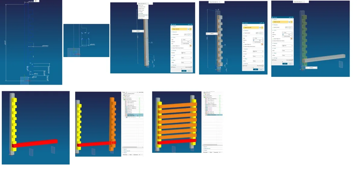
") of the groove and a pattern (n-1) of the line quoted step. the second sketch only has the depth of the list pl.
of the groove and a pattern (n-1) of the line quoted step. the second sketch only has the depth of the list pl.
")