volaff
Guest
Hello everyone again.
I would have a question for the most experienced.
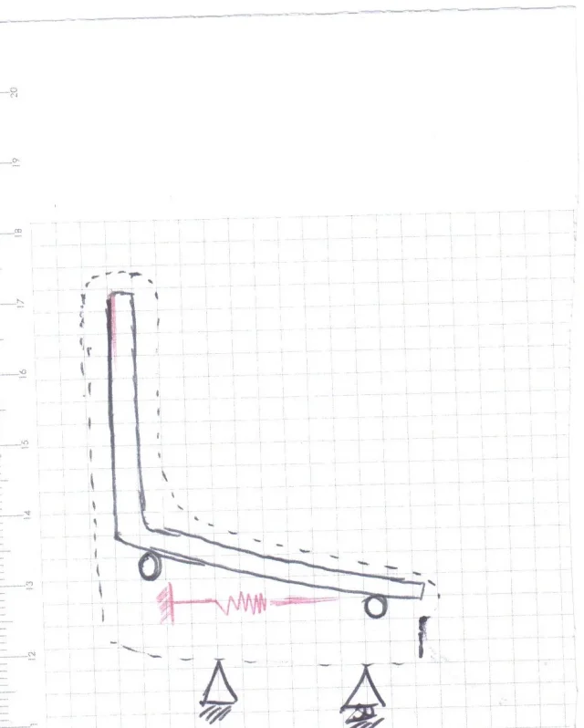
a seat mounts, by default, an elastic locking gas spring with a f1=100n though, due to the type of locking, tends to let the seat slip.
for a test we mounted on the same seat a gas spring with rigid compression locking with a f1=200n and we noticed two things.
1. with such spring it is practically impossible to move the seat (and there can be being the f4 force in compression about 365 n
2. If the passenger is not sitting on the seat he returns to position very slowly while if the passenger is sitting the seat does not move precisely yet I have a force f1 of 200 n instead of 100 as the original spring.
Where is the hippo according to you?
Thank you very much to anyone who wants to answer.
I would have a question for the most experienced.
a seat mounts, by default, an elastic locking gas spring with a f1=100n though, due to the type of locking, tends to let the seat slip.
for a test we mounted on the same seat a gas spring with rigid compression locking with a f1=200n and we noticed two things.
1. with such spring it is practically impossible to move the seat (and there can be being the f4 force in compression about 365 n
2. If the passenger is not sitting on the seat he returns to position very slowly while if the passenger is sitting the seat does not move precisely yet I have a force f1 of 200 n instead of 100 as the original spring.
Where is the hippo according to you?
Thank you very much to anyone who wants to answer.
")