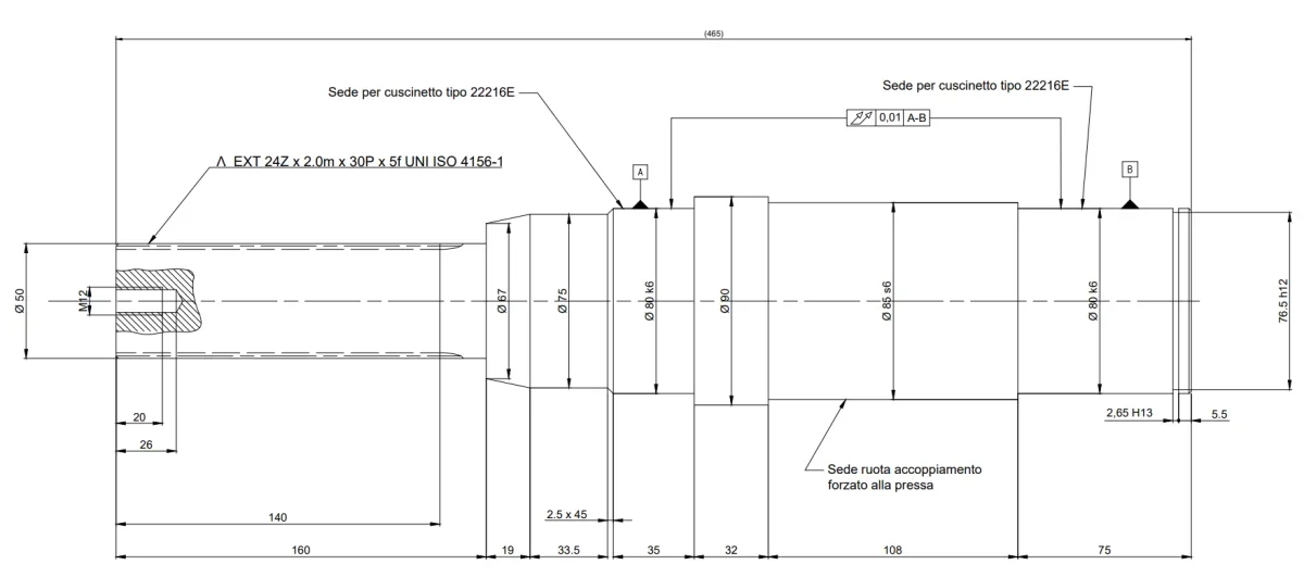
on the drawing you sent I have the following doubts:
1) lack surface roughness
2) the elastic ring seat I would quote it from the shoulder rather, I link you a video about it (
)
3) As for bearings if they have to support axial loads I would also estimate a geometric tolerance of double oscillation on the shoulder where they go to a bar
4) I would also make a check, from skf catalog, if the minimum shoulder straps are respected
5) the datum a and b is better to place them referred to the diametral quotas
6) the s6 tolerance on the phi85 diamtero can go well, with h7 hole you have a link with interference
7) I personalmte (but I only speak to you with study experience and non-work) would not put any further geometric tolerances on the coupling diameter with the wheel
8) the channel I do not have the rules under hand but I think it can go well as indicated
9) the indications for the seat, wheel etc. do not serve according to me in the drawing of particular