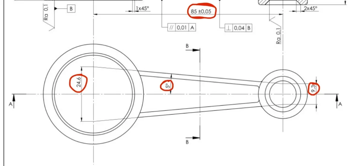
I tried to make it scholastic enough to avoid making big mistakes, surely the bevel on the big hole and the big ray fittings will add them.
some considerations besides those that have already been made.
in the quotation, tolerances, surface roughness it is necessary to consider the material with which the particular will be constructed, the function of each part and the working cycle.
with reference to the numerical references shown on the attached drawing, I propose some considerations that should always be made in advance.
It is a question of defining whether this tree will undergo a surface hardening treatment after turning, or if it is sufficient to use an already reclaimed steel. in the first case all diameters and relative shoulders must be rectified as the treatment creates deformations and surface finishes that affect the functionality of this element.
In this case, given the type of application, I would say that it is a cementing and tempering steel (e.g. 20mncr5 or 18nicrmo4), to be indicated in the table below the design.
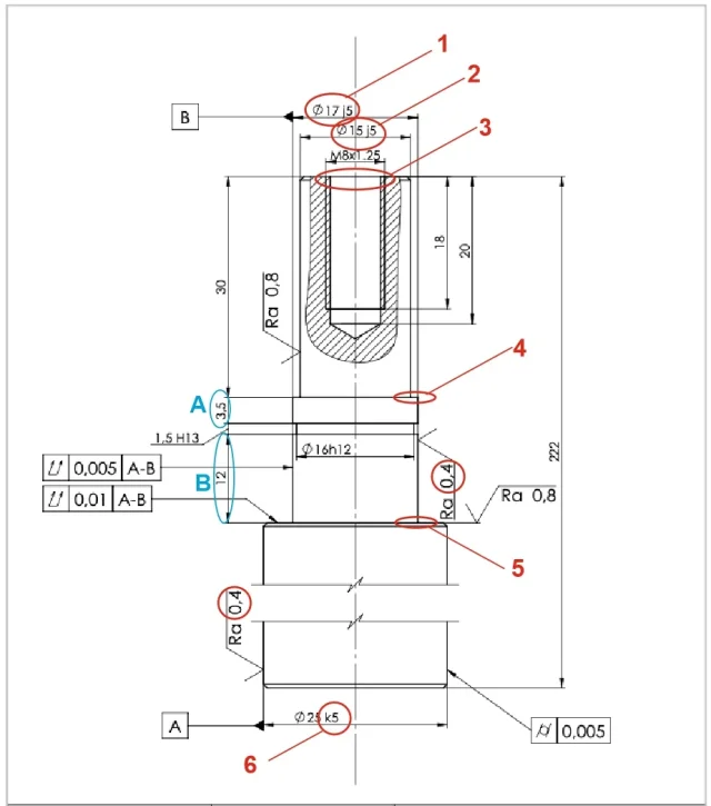
1) diameter 17. Given the presence of the bar seeger seat, this will certainly be a diameter where a bearing will be mounted, so the tolerance can be checked in the appropriate tables (j6 for normal loads).
as earthly roughness 0.8 for all rectified parts, unless there are particular requirements of extremely accurate surfaces for which a lower roughness needs (obtainable at higher costs).
stroke b refers to the bearing seat (17 j6) while the tract a could be referred to the diameter on which the lip of a seal ring acts; In the affirmative case it is necessary to foresee for this section (now 3.5 not compatible with the design) an f7 tolerance that facilitates the assembly of the cold bearing. In this case it is necessary to also foresee a 1x30° bevel to facilitate the assembly of the sealing ring and to avoid the danger of damage of the lip.
2) for diameter 15 tolerance could be j6, h6, k6 or different if you need a coupling with a lock for interference; It is about seeing what is mounted in that position.
3) you have already highlighted the lack of the bevel; when you do consider that the piece will be mounted on the counterpoint on that side when turning and grinding.
4)-5) you have already reported the lack of rectification gorges. in point 4) is not indicated the roughness (0.8) of the countertop.
6) also here, apart from roughness 0.8, for tolerance it is a matter of seeing what should be cast on this diameter and whether it is subject to normal or heavy stresses.
Sorry if I have stretched a bit, but it is to make you understand better (although in a summary way) that when drawing a component it is not only a matter of making a drawing, but it is necessary an analysis as complete as possible of the function of that particular in a particular application and act accordingly.