• This forum is the machine-generated translation of www.cad3d.it/forum1 - the Italian design community. Several terms are not translated correctly.

how to indicate the selective surface tempering

  • Thread starter Thread starter max&cad
  • Start date Start date

max&cad

Guest
Good morning to all,
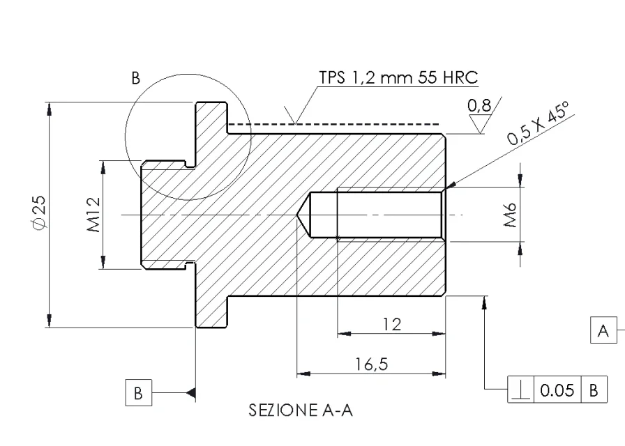
I tried to search everywhere on the net but without success... I admit I'm inexperienced and so I ask for the help of those who know more about me in thermal treatments. I have to make a small pin/shaft in c45 on which rotates a toothed pulley through self-lubricating bushings. the bushing manufacturer suggests a hardness of 55 hrc and then with the supplier we decided to make a superficial selective tempering. in the drawing I simply wrote "tempra" above the indication of superficial roughness (0,8) but I would like to indicate it more clearly... Help me?Screenshot 2024-09-05 110111.webp
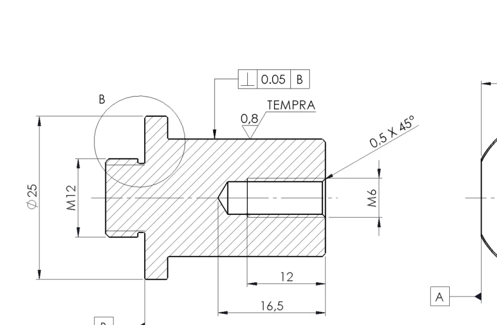
 
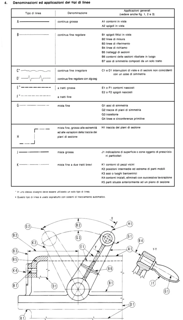
when there is a surface treatment only on in part of element you draw a line, stretch long short stretch seems to me, over the area to be treated. above the cartilage or in other clearly visible area indicate the specifications of the treatment.
already talked about it in the forum somewhere
 
thanks massive, I searched long and wide on this forum but I didn't find... I have found this site directions to design thermal treatments where to get what to indicate on the drawing board but I do not understand in my case how to do... in other parts of the internet I found written that if the tempra is massive it is indicated to cartiglio, while if it is selective it is indicated in the area to be treated... but I didn't understand
 
 
I read this but I didn't find an answer to my question... I did a test: do you think it's okay?Screenshot 2024-09-05 114950.webp
 
letters indicating geometric references and/or details must be unique.
the meaning is understandable the same, but if you want to maintain a minimum of formality... do not use the same letter to name different entities.

if the object is asymmetrical... draws a dotted line on both sides.

to indicate a heat treatment of tempering you must indicate a hardness interval (correct for tempering in hrc) and a range for the depth of tempering.
to be predicted overmetal to perform grinding, after tempering.
add a drain throat to the shoulder to ø25.

personally gives me on the nerves not to see the indication of the diameter on the worked part, but at school they still teach so...


Given the geometric dimensions and simplicity, the starting material could be a reclaimed c45 bar.
 
I read this but I didn't find an answer to my question... I did a test: do you think it's okay?View attachment 72019
the surface is indicated with long lnea one or two long line lines as all the delimitions of areas, thickness 0.5.
- if the surface is before tt
- if it's over.
you can use the symbol of roughness and write to us but it is not ideal.
you make the note with arrow pointing to the definition line and you write "see note" depending on whether you have the appropriate space in cartilage or not.
Note: Induction surface tempering 54/56hrc depth 1.5mm.
 
Last edited:
the surface is indicated with long lnea one or two long line lines as all the delimitions of areas, thickness 0.5.
- if the surface is before tt
- if it's over.
you can use the symbol of roughness and write to us but it is not ideal.
you make the note with arrow pointing to the definition line and you write "see note" depending on whether you have the appropriate space in cartilage or not.
Note: Induction surface tempering 54/56hrc depth 1.5mm.
thanks to mechanical heartmg,
at the end I followed the indications of this website (what I indicated at the beginning...) and the supplier understood.
 

Forum statistics

Threads
44,997
Messages
339,767
Members
4
Latest member
ibt

Members online

No members online now.

Back
Top