• This forum is the machine-generated translation of www.cad3d.it/forum1 - the Italian design community. Several terms are not translated correctly.

import step together: invisible parts

biXel

Guest
Good to all.

as some may recall, I have been a nx user for several years; However, I am trying inventor 2024 to make usability comparisons between the two..
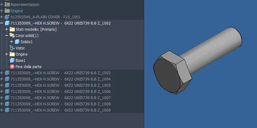
I started with a simple import of a set in step format and already find 'difficulties'.
In fact, to import finished (a simple 'open' in reality with some parameter to set before confirming the operation ) the parts of the axieme seem to me to be set as if they were hidden.

I'm trying them all, but without success. . .

Do you have any suggestions?
import_step_result.png
Thank you very much to all:)
 
without part available I go a little 'at home: did you open the browser folder "solid bodies(17)" and verified from there that the various bodies are set as visible?
 
without part available I go a little 'at home: did you open the browser folder "solid bodies(17)" and verified from there that the various bodies are set as visible?
Hello, catafract.

Actually to me they always seem 'greyed out'.. .

I attach the step file; it can definitely be helpful (change file extension in . stp )
Thank you very much.
 

Attachments

1719057004865.webpI have fewer bodies (ok, I see the different code): I confirm that you only have to set "visible" the flag (set dx on the body or set of bodies). I don't know how to tell you why they charge me with such unchecked flag and so I don't see anything, but then you can easily fix it and let me know if you can.. .
 
I figured it was something like that, but I'm really getting closer to inventor now.

Can you tell me what settings you set in the step opening phase?
I'm using the ones I'm practicing here in the post.settings_inventor.PNGI'm noticing that once imported, I don't have the tree of the parts like what you show.
tree.PNGIn addition, I add that the command you cite seems to me activated on the parts.. (see below)
visibility.pngBesides, I do not understand why in solid works and nx at the end import of the same step immediately shows me geometries.
inventor is acting like this....
Do you know if there is a default settings that can be set to show geometries automatically in these cases?

Thank you very much again:)
 
Last edited:
It seems to me to coincide, as to the solids not visible ever happened so perhaps it has to deal with export but of course it can be happened others who have more precise information. I would tell you to try to scourge the surfaces, but still my setting led to your own results
1719059557705.webp
 
but no one waits: We're importing the same file.
so I don't think you can have different behaviors at equal settings.
I expect the tree of the parts to be the same once the step is opened, but they seem different to me.
Did you notice?
Isn't there any 'views' to activate in the tree? any display mode of the tree of the parts?

What version of inventor are you using?
Thanks :)

I added a video where I show what I do. tell me if I have to proceed differently (name extension in .mp4 ).
 

Attachments

Last edited:
I explained badly: when the amount is all gray and you do not see anything, just like you. I don't understand this behavior I've ever seen.1719063560641.webppoi:
  1. spinning the posterline "corpi" (bodies per te)
  2. select the various bodies (bodies), which have imported correctly
  3. dx mouse button > I select the "visible" item in the context menu, change the color to the icon and display what I want.1719063681852.webp
 
the fact is that that folder that should contain solids to me does not appear (in fact I put the video just to show this thing ).
😒
 
I think I understand why the body is hidden: This is the layer on which they are allocated.
Now, I'm trying to figure out... where the layers are activated/disabled in all tabs of the program... but I can't find it.
where is the command that shows me the list of all layers in 3d environment and then turn on/off those that interest me?
Thanks :)
 
ok, my magazine: I stayed at your first screenshot where you had the solid multibody.
I usually drag the step file from the windows shutter together and the import window actually grants the choice between together and multiporp, while the process you followed does not.
the imported step in this way becomes a set: in this case you have to open each generated part and follow the same process described before. in inventor there are no layers of solids, or at least I have never heard of them: visibility (and other) are characters related to the individual element.
see: I entered into editing in the part and made visible the solid (at this point the only) contained in it1719122641648.webp
 

Attachments

  • 1719122536218.webp
    1719122536218.webp
    28.9 KB · Views: 1
  • 1719122568323.webp
    1719122568323.webp
    31 KB · Views: 1
good of :)
ok later I try as you indicated me.

so in inventor de want to allocate parts on layers different from each other that is not feasible?
in these cases then the user must hide / make visible every single part time at a time? 🤔
 
I just tried dragging the step into the inventor; It doesn't seem to change much.
In one case it doesn't even do anything.
I have attached a zip with inside two short videos with the operations I perform.

Could you tell me better how you do it?
Thank you very much.
 

Attachments

so in inventor de want to allocate parts on layers different from each other that is not feasible?
in these cases then the user must hide / make visible every single part time at a time? 🤔
I don't know nx, I guess he has very different procedures. with regard to the visibility of parts and together (and colors, transparencies, etc.) the visual representations are used: you create and configure at will, on youtube you find various tutorials.
as to your procedure is right here:1719132538168.webpyou can choose whether to import as a whole or multibody: we have the same results. what you miss is a double click on the part in the browser tree so you can access its editing and configuration of the various parameters. you can also do dx>apri key to have the file in direct editing on window apart, and in this way the changes to visibility will be persistent and not tied to the axieme... but here we are running. open aside, change visibility and save.
 
catafract,
if you have seen my videos, when selecting the step and opening the configuration panel for the import, the drop-down menu that you show just above is not editable and is fixed on assembly.
I have not yet been able to see the parts importing the axieme...if not making open on each single component and then activate the visibility on each single component opened in 'sede separated' .
only so I can then see the components in the main axieme; However, I think it's not exactly the right approach. If I had a set with 100 parts, I'll shoot myself. .

Can you tell me the steps you follow? or maybe a short video?
You would help me not little.
I've been looking for yt since this morning, but everyone starts from a beautiful set with visible parts. . .

Thank you very much.
 
as I have already told you I do exactly what you do and I get exactly the same results, and to activate visibility I do like you (as I wrote you above) entering the part, in this sense I can not help you any further, but tomorrow you will see that someone with alternatives jumps out.

as to the parts set to not visible after the import, I repeat that it never happened to me, to the limit with some superfice but solid never: and I have passed many.

try downloading some steps from the internet, from suppliers sites and see what happens: could also have gone wrong something export side. . .
 
ah ok, then I understood whistles for whistles ,
Mah, you see that in inventor this step is antipatic ,
I just tried with sw and creo. sw displays the parts immediately, while I create the layer 200 disabled and activated with a click.
mystery of the inventor(s). g
a thousand and good evening 🙂
 
catafract,
if you have seen my videos, when selecting the step and opening the configuration panel for the import, the drop-down menu that you show just above is not editable and is fixed on assembly.
I have not yet been able to see the parts importing the axieme...if not making open on each single component and then activate the visibility on each single component opened in 'sede separated' .
only so I can then see the components in the main axieme; However, I think it's not exactly the right approach. If I had a set with 100 parts, I'll shoot myself. .

Can you tell me the steps you follow? or maybe a short video?
You would help me not little.
I've been looking for yt since this morning, but everyone starts from a beautiful set with visible parts. . .

Thank you very much.
if you have already tried to import a step file, delete the result and try again to make the import wanting to use different settings, inventor "maintains" in memory the previous setting for which the result does not change. You must necessarily make a new set and try to import the step cn a different configuration.

As for non-visible solids, once the step is opened, for example, as together you can try to select -> default -> button dx -> all visible elements. In this way you should turn on all the solids off.Immagine.webp
 

Forum statistics

Threads
44,997
Messages
339,767
Members
4
Latest member
ibt

Members online

No members online now.
Back
Top