You are using an out of date browser. It may not display this or other websites correctly.
You should upgrade or use an alternative browser.
You should upgrade or use an alternative browser.
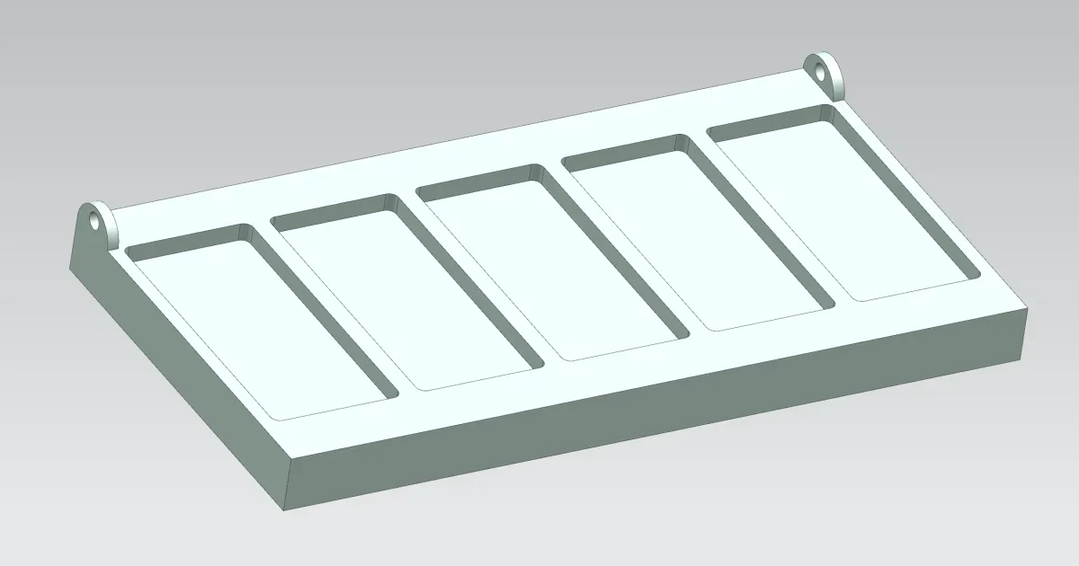
injection moulding component with holes
- Thread starter ET3D
- Start date
-
- Tags
- inizione stampaggio
francescodue
Guest
without dimensional indications cannot be hypothesized.
How thick are those wings?
is it a full plate with only the tanks you see?
is it possible to download the material on the other side?
can you change the geometry of the piece?
in case of the third question, you can make the holes for intersection of the two parts, fixed and mobile, of the mold. precision remains high, but some small trunk can be formed in the area where the two profiles close (depending on the precision of the mold and the printer).
Vittorio
Guest
you can do what you ask.. without movement.Good morning, I am new in the injection molding environment and I would like to ask you an opinion/choice. in the piece that I attached there is a way to create the side holes (no need to be precise) without using movements ? thanks a thousand
if you want to write
I'm sorry, you signed up today and I don't want you to be the classic meteor who asks and then disappears.
Last edited by a moderator:
ET3D
Guest
Hi.
thanks for your answers, quiet victorious, don't worry")
Anyway I'm out of the house and that's why I can't answer / I'm putting a lot.. .
Frankesco to answer:
1- we had designed it with an emptying of 1.5 mm, as I usually work with thermoforming molds and usually the thermoform thickness is1/1.5mm.
But if you want, we can make it full if you can print it with holes.
2- it is possible to change the geometry of the piece, for me the important thing is to stay in the dimensions of the maximum that the customer has given me, that there are the rectangular seats you see and that there are those holes, if there is to change something between which thicknesses etc.. I can do it the important thing is that it comes out....
However what I have screentao was a quick draft because I wanted to understand if it was feasible technically, I should finish the piece also s and I do not have much dimesticity in engineering on injection molds.
The only thing I had in mind was to cross the parts as you say or use the cumsas, but I don't know how to move sincerely:/
thank you guys
thanks for your answers, quiet victorious, don't worry
Anyway I'm out of the house and that's why I can't answer / I'm putting a lot.. .
Frankesco to answer:
1- we had designed it with an emptying of 1.5 mm, as I usually work with thermoforming molds and usually the thermoform thickness is1/1.5mm.
But if you want, we can make it full if you can print it with holes.
2- it is possible to change the geometry of the piece, for me the important thing is to stay in the dimensions of the maximum that the customer has given me, that there are the rectangular seats you see and that there are those holes, if there is to change something between which thicknesses etc.. I can do it the important thing is that it comes out....
However what I have screentao was a quick draft because I wanted to understand if it was feasible technically, I should finish the piece also s and I do not have much dimesticity in engineering on injection molds.
The only thing I had in mind was to cross the parts as you say or use the cumsas, but I don't know how to move sincerely:/
thank you guys
Vittorio
Guest
if the designer allows it, this could be a system (as perhaps already suggested) not to use movements


ET3D
Guest
Thank you for the speed of the answer!
However, I think it's a great solution that you're proposing, it's gonna look like a trivial thing, but thanks for the screens now it's very clear to me
Can I ask you even if I have to consider minimum thicknesses if what?
Thank you very much
However, I think it's a great solution that you're proposing, it's gonna look like a trivial thing, but thanks for the screens now it's very clear to me
Can I ask you even if I have to consider minimum thicknesses if what?
Thank you very much
Vittorio
Guest
here we enter the field of stresses and not knowing the use of your object I do not feel like shooting random numbers.
But... the important in the design of a plastic or aluminum piece is to always keep constant thicknesses and avoid sharp differences of thicknesses.
the mold must not have alive edges.. Generous rayings are a twist both to facilitate the flow of the material during injection and for the duration of the mold.
ET3D
Guest
Thank you very much victorious!
Tomorrow when I get back to the office I try to finalize the piece according to the advice you gave me!
I keep you updated
However the holes do not serve as precise as I said because they only have to be a guide to insert a door that needs to open and close laser cut in petg.
I have always sought a way to learn the design of injection molds and steps to do also to cad, such as the extraction of closures etc... I found little and nothing online.
Is there any documentation or any way to imply this kind of competence without having someone directly explaining it to you?
Thank you
Vittorio
Guest
ciao @et3d Since you're new to the job, I'd like to give you some advice that might help you in your professional career.
Many designers have little knowledge of die casting/injection and this penalizes the object itself to produce.
some 3d models do not even have the moldings and therefore they must be completely remodeled by the molder.
other important thing that few designers consider, are tolerances.
generally the designer performs the 3d model of the piece with the nominal quotas, and then makes a nice design 2d adding the tolerances, which until they are centered (example 10 ±0.1) little change, but if they have different deviations (example 10 +0.1/0) you have to intervene on the model to fix it and this procedure is not easy especially on a step file.
therefore my advice is to consider what is said and model with the nominal quota 10.05 ±0.05
As for how to make closures there is no school of thought/tutorial, it is a bit like building a 3d model.
the same model you posted at #1, if 3 different people modeled it, 3 different chronology trees would come out.
we say that the imagination of each of us is decisive, combined with the tools offered by the software used.
in any case the closing traces and the moldings, affect the aesthetic or functional aspect of the piece.
summary:
if you have no experience of molds, it would be wise to see who builds them to get a piece with a great price/performance balance.
I hope I've been helpful
Hi.
ET3D
Guest
Hello victorious,
Thank you very much for the advice! I will keep in mind what you told me and try to bring it back to my models.
Thank you very much
Good day
Thank you very much for the advice! I will keep in mind what you told me and try to bring it back to my models.
Thank you very much
Good day
francescodue
Guest
I allow myself to add something to what is said by victorious.
In addition to the question of quotas, the order with which the various processing operations are carried out becomes important.
for example in the piece in question you will have to add the molding to obtain the piece from the mold. normally a reference plan is held, the one in which the mold is closed, from which the various forms start. depending on how you proceed you may find yourself or too large thicknesses, which can lead to aesthetic or mating problems, or too thin, which make the details fragile.
In some cases the cad may fail geometry because some surfaces come to be in absurd positions.
this also happens with rays.
I suggest you visualize the piece in mind, as you would like, and proceed with the various steps (extrusions/cuts, sformings, rays, etc.) so as to add details on "sicure" geometries.
ET3D
Guest
hello francesco, thank you for the advice. this morning I will try to fix the piece taking into account everything you have told me
ceschi1959
Guest
what you say is convenient to the molder but is misleading and dangerous to the designer. the example is that of a couple in which I have to guarantee or interfere or play. Secondly when you make a cp/cpk on important odds or even criticism by putting a tolerance ± I can't understand where my process goes.generally the designer performs the 3d model of the piece with the nominal quotas, and then makes a nice design 2d adding the tolerances, which until they are centered (example 10 ±0.1) little change, but if they have different deviations (example 10 +0.1/0) you have to intervene on the model to fix it and this procedure is not easy especially on a step file.
therefore my advice is to consider what is said and model with the nominal quota 10.05 ±0.05
I've never given a detail devoid of sforms and closures and injection points, perhaps discussed first with the moldist, the designers who do not should cut their hands ..
Vittorio
Guest
I understand your problem and you're not wrong, but for those who build the mold it's not easy to handle.
If they are interattentive positions the problem does not exist, but if they are walls with relative beams and against rays the modification is very challenging if not rebuild the model.
Let us make an example:
on a coupling h7/g6
100 h7 (0.04/0)
100g6 (-0.01/-0.03)
If the 3d is built at 100.02±0.02 and at 99.98±0.015 I think the result is identical.
worsening for the molder because it tightens the field of tolerance...but this is a solveable problem.
many cads have the automatism to center and balance tolerances, a reason there will be.
ceschi1959
Guest
So I should make two models and two drafting: one for the molder and one for quality control? in the example you brought the h7 is on a drafting and g6 in another. suppose that the designer of the detail is replaced with another, if he sees a h7 straightens the ears and checks the coupling, if he sees a 100.0175 ± 0.035 (it7 0.035 mm) he thinks of a sadistic designer. . .I understand your problem and you're not wrong, but for those who build the mold it's not easy to handle.
If they are interattentive positions the problem does not exist, but if they are walls with relative beams and against rays the modification is very challenging if not rebuild the model.
Let us make an example:
on a coupling h7/g6
100 h7 (0.04/0)
100g6 (-0.01/-0.03)
If the 3d is built at 100.02±0.02 and at 99.98±0.015 I think the result is identical.
worsening for the molder because it tightens the field of tolerance...but this is a solveable problem.
many cads have the automatism to center and balance tolerances, a reason there will be.
in the reality in which I work, with molds also from hundreds of thousands of €, we discuss in advance with the moldist, quota per quota, disform to disform, injection and so on.
in other realities that I worked for I felt the designers say 'se rangia el moldista' and then find pieces that did not mate because the sforms were made starting from one edge instead of another.
the position of the extractors must also be discussed.
In my view, therefore, there must be maximum cooperation between the various bodies in compliance with their competences.
p.s. I absolutely do not want to turn on flames nor show who has it anymore ... collaboration and mutual respect are my motto.
Last edited by a moderator:
Vittorio
Guest
bhe.. No.So I should make two models and two drafting: one for the molder and one for quality control? in the example you brought the h7 is on a drafting and g6 in another. suppose that the designer of the detail is replaced with another, if he sees a h7 straightens the ears and checks the coupling, if he sees a 100.0175 ± 0.035 (it7 0.035 mm) he thinks of a sadistic designer. . .
in the reality in which I work, with molds also from hundreds of thousands of €, we discuss in advance with the moldist, quota per quota, disform to disform, injection and so on.
in other realities that I worked for I felt the designers say 'se rangia el moldista' and then find pieces that did not mate because the sforms were made starting from one edge instead of another.
the position of the extractors must also be discussed.
In my view, therefore, there must be maximum cooperation between the various bodies in compliance with their competences.
p.s. I absolutely do not want to turn on flames nor show who has it anymore ... collaboration and mutual respect are my motto.
the example I indicated you could be a g6 pocket and a h7 prisma.. all on the same 3d/2d
I will tell you that with regard to the automotive sector I always receive the 3d models centered on tolerance, with deformations and expeller positions.
the model is ready to use.
for other sectors there are listed issues and exchanges of dozens and dozens of emails to understand how to intervene.
I have to say that you _ You're a rare pearl that works with molders.
Thank you on behalf of the category.
Last edited by a moderator:
ET3D
Guest
Hey, guys.
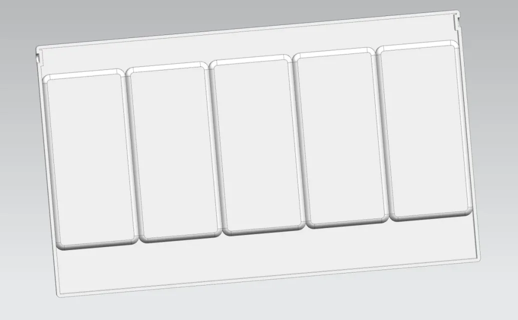
I fixed the piece for the size it should have.
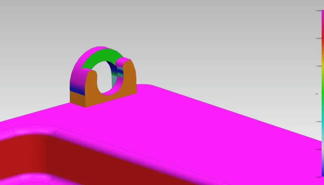
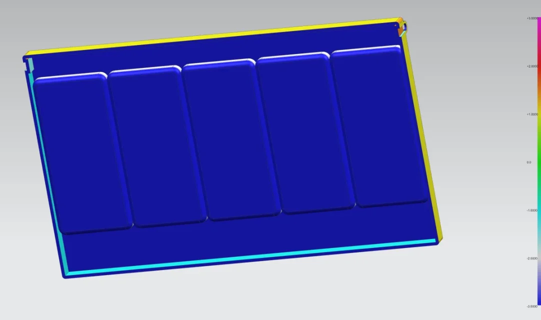
I found some difficulties on how to properly shape the parts because I saw cad conflicts and generated an incorrect geometry (talk of the section that shared me victorious) I therefore remain under squadrons in that area, in addition to the fact that perhaps they still play too much on the thermoforming molds that I am accustomed to see, so I don't understand well if the tank so full is printable or there is need to apply a blanking material. (in this case 1)
I don't even think I've done the points that need to meet between the matrix and the punch to create the hole. I'm cruising too much on something that technically is simple maybe and I'm thinking too much going to wrong simple things.. .
I attached a step for those who want to take a look at him.
Thanks
I fixed the piece for the size it should have.
I found some difficulties on how to properly shape the parts because I saw cad conflicts and generated an incorrect geometry (talk of the section that shared me victorious) I therefore remain under squadrons in that area, in addition to the fact that perhaps they still play too much on the thermoforming molds that I am accustomed to see, so I don't understand well if the tank so full is printable or there is need to apply a blanking material. (in this case 1)
I don't even think I've done the points that need to meet between the matrix and the punch to create the hole. I'm cruising too much on something that technically is simple maybe and I'm thinking too much going to wrong simple things.. .
I attached a step for those who want to take a look at him.
Thanks
Attachments
Vittorio
Guest
red color walls are without sform
I don't know what material you need to print, but a thickness 5mm is excessive.
you have to find a system to empty the inside and make the sections constant without sudden changes in thickness. You can't print will make a lot of sucks.
Did you read the rules I sent you to post #8?


I don't know what material you need to print, but a thickness 5mm is excessive.
you have to find a system to empty the inside and make the sections constant without sudden changes in thickness. You can't print will make a lot of sucks.
Did you read the rules I sent you to post #8?
ET3D
Guest
hello victorious, always thanks for the quick answer.
I still couldn't take a look at the document you sent me, as soon as I read it.
Unfortunately, as all things have asked me this urgency together with all the other already accumulated and so I have not been able to look at it. But surely this evening I will read it.
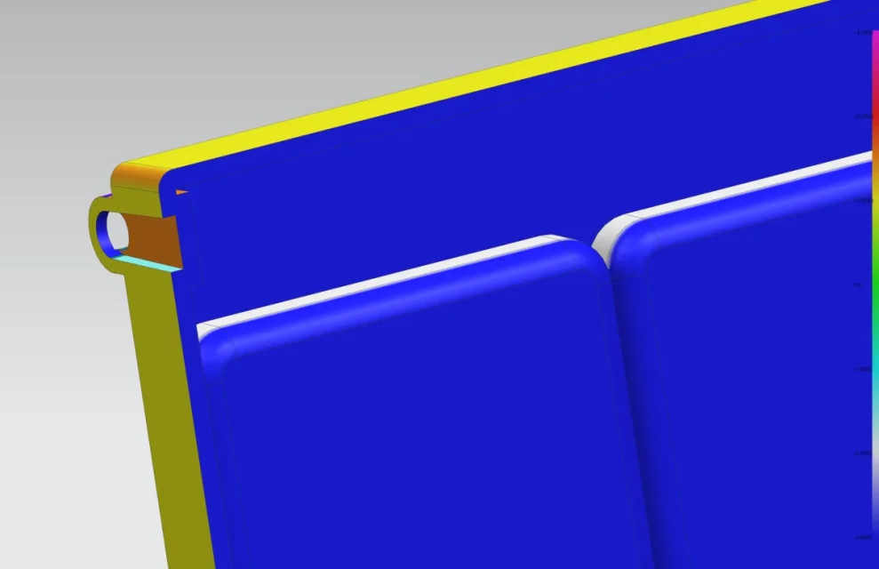
However as I wrote above I did not distort that area because I do not understand how to do, allego of the screens that I did with the evaluation of the corners of disform, the geometry is wrong and in some areas even with positive degrees.
the material in which we thought to print it was 1 mm thick transparent petg, but if I have to think about making a thermoforming mold with that thickness I do not grow the sufficent walls to make the separations between the rectangular seats so it is for what I did not understand very well the operation.
having made only injection moulds for the automotive they already gave me the engineered and ready piece and therefore I never dwell on the part of co-design to engineer the piece... :
I still couldn't take a look at the document you sent me, as soon as I read it.
Unfortunately, as all things have asked me this urgency together with all the other already accumulated and so I have not been able to look at it. But surely this evening I will read it.
However as I wrote above I did not distort that area because I do not understand how to do, allego of the screens that I did with the evaluation of the corners of disform, the geometry is wrong and in some areas even with positive degrees.
the material in which we thought to print it was 1 mm thick transparent petg, but if I have to think about making a thermoforming mold with that thickness I do not grow the sufficent walls to make the separations between the rectangular seats so it is for what I did not understand very well the operation.
having made only injection moulds for the automotive they already gave me the engineered and ready piece and therefore I never dwell on the part of co-design to engineer the piece... :