roberta.f
Guest
Good morning to all, I've been following the forum for a while, but this is the first discussion I open, so I introduce myself briefly:
I am a mechanical engineering student, next to the three-year degree, use solidworks for a couple of years, but exclusively in the field of university projects, so I have no particular technical experience.
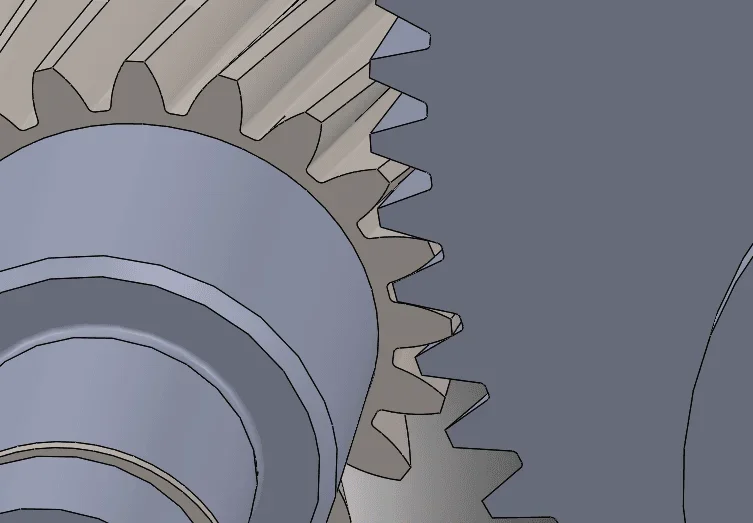
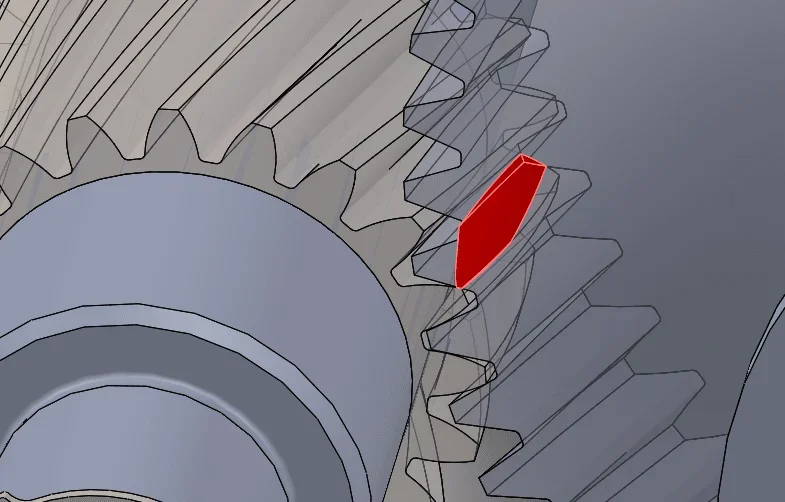
I am currently working on the project of a parallel axle reducer with helical wheels. the project is practically ready, but regarding the model on solidworks I still have uncertainties regarding the couplings between the wheels. the constraints I set are the intersection and a gear mate between the pairs of trees, but it is practically impossible to position the wheels so that there is no interference between the teeth. the wheels are taken from the toolbox, so the coupling should be right, but I can't set any tangency that does not create interference. I didn't find any such discussions and the professor didn't help, but it requires that there are no interference.
 I don't know if there's a solution or you should leave everything as it is.
Thank you so much for your attention!
I am a mechanical engineering student, next to the three-year degree, use solidworks for a couple of years, but exclusively in the field of university projects, so I have no particular technical experience.
I am currently working on the project of a parallel axle reducer with helical wheels. the project is practically ready, but regarding the model on solidworks I still have uncertainties regarding the couplings between the wheels. the constraints I set are the intersection and a gear mate between the pairs of trees, but it is practically impossible to position the wheels so that there is no interference between the teeth. the wheels are taken from the toolbox, so the coupling should be right, but I can't set any tangency that does not create interference. I didn't find any such discussions and the professor didn't help, but it requires that there are no interference.

 I don't know if there's a solution or you should leave everything as it is.
Thank you so much for your attention!
