• This forum is the machine-generated translation of www.cad3d.it/forum1 - the Italian design community. Several terms are not translated correctly.

minimum distance hole-bord stainless steel sheet

  • Thread starter Thread starter Wintel
  • Start date Start date

Wintel

Guest
Hello, everyone. I wanted to ask a question.
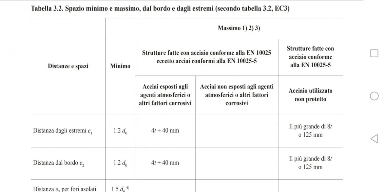
I made a rectangular plate with a set of holes (about thirty) along the perimeter. the distance between the hole axis and the edge is 20 mm and the thickness of the sheet is 10 mm, while the holes have a diameter of 15 mm.
I have a doubt about it and going to look at Eurocode 3, I read that the minimum distance must be 1.2 times the diameter of the hole.
my question is: as the 304 aisi sheet, are these indications valid?
 
Why shouldn't it be worth the inox?
What do you say? accurately Eurocode 3? refers to types of material or characteristics that can lead to exclude certain materials?
from what I read, if we speak of the same paragraph, he says:p(1) the distance from the edge e2 , from the center of the hole of a joint device to the adjacent edge of any part, orthogonally measured to the direction of application of the load (see Fig. 6.5.1), should not normally be less than 1.5 d0 .
p(2) the distance from the edge can be reduced to a value not less than 1.2 d 0 provided the design resistance to recroaching is reduced accordingly as indicated in 6.5.5 or 6.5.6.
Therefore it does not talk about types of material, but to give you a correct answer you must first tell us the function of the hole, which is the direction of the load and if the resistance of the recroaching allows you to maintain that distance.
that the material is stainless makes sense only according to the calculations you should make
 
I attached a screenshot. I insert the image because the minimum distance is shown in the table. in the same leg that is valid for materials in accordance with the norm en 10025, which is the norm regarding the designation of structural materials. But maybe I'm wrong.

coming a moment to the function of the holes. this plate is fixed to a wall with a thirty screws and on this plate a machinery of about 1000 kg is set to a swing. This machine can have small oscillations (during operation) both vertically and horizontally. screws are therefore subject to traction and joint also to cut, due to the weight of the machine.
 

Attachments

  • Screenshot_20200810-094811.webp
    Screenshot_20200810-094811.webp
    45.6 KB · Views: 80
I'll write it up. being the holes arranged perimeter to the rectangular plate, it goes from itself that on two sides it is necessary to leave at least 1.5 times the diameter of the hole. on the other two at least 1.2 times the diameter of the hole. or at least I think I understand.

I'm losing myself in a glass of water.
 
the norm of reference in Italy are ntc2018 that is low on eurocode, but it is not the same thing. the urocodice in Italy has no legal value (in principle, but it is not the case of pointing on the thing).

ntc establish that the minimum distance from the hole center on the plate is 1.2 times the diameter of the hole. in your 18mm case, you have 20mm then check satisfied.

but this does not mean that the plate so perforated is suitable to hold the load. the appropriateness of the plate and its holes should be verified by analytical calculation.

silly example. the ntc also establish that the structural bolts must have a minimum size m12. but that doesn't mean that a single m12 bolt reggas any kind of load.
 
thanks for the clarification. then the reference is ntc 2018.
with regard to analytical verification, do you mean that the resistance to the cut of the vines and to the recroaching must be checked?
 
exact, it serves an analytical audit of the fixing composts.
the norm says only that for example even in case the load was only 0.1kn, and the analytical verification was met even only a bolt m14 in hole diameter 15 with center distance from the edge 10mm. in any case you must increase this distance to 15*1,2= or 23mm. but does not guarantee in any way that this measure is adequate to any type of load. will be the cost of the designer to verify size and position of the components.
 
Forgive me, I'm lost. Why should we increase the minimum distance to 23 mm? However, yes, I try to make two calculations according to the law.
 
the distances of the holes from the edge are nornate:
- one cnr 10011 expired but can give an idea
- uni en 1993 eurocode 3
- ntc2018
the indications are dictated to ensure an adequate propagation of the efforts, moreover to ensure that no weak areas are created, where the material is revolved or ironed.
clearly it is necessary instead to make the check of seal of the bolted joint that is instead the ability to carry the load.
 
So I have to increase the distance? because the above rules give slightly different indications.
 
the distance from the edge is perhaps the last of the problems; in my opinion it would be enough to strengthen the edge, weld a band of 5mm or making a closed fold, if possible on a thickness of 10mm, to increase its resistance. By the way, the norm doesn't talk about thicknesses, it seems to me, but I think it's different a screw 15mm on a thickness of 10 instead of a thickness of 2...

However you have 3 screws fixed in the wall: What are these screws in? 5.6? 8.8? 12.9? or are they mechanical dowels?
Is the wall true reinforced concrete wall or is there drowned a threaded plate?
The load is up, but how much? 1000kg are leaning 20 cm from the wall or 1 meter?
Are there any reinforcements on the sheet to prevent the ribbing of the shelf?

In short, the part that could yield is not said to be the sheet due to the failure of the edge
 
multicitation of mobile messages is a struggle.

then, tomorrow I try to post analytical calculation here in the discussion to check if the conditions of resistance are met.

If I don't go wrong, when you go to calculate the recroaching resistance, the thickness appears. However, the screws are of the m14 steel a2-70 and this plate is fixed on another threaded plate drowned in the reinforced concrete.
the load is distributed for about 2 and a half meters, maybe even 3 meters. we say that the remaining part of the machine is all boxing and it is precisely from this consideration that, according to me, the most vulnerable zone would be precisely the fixing of the plate to the "coated" plate.

p. s. the thickness of the plate in question is 10 mm.
 
I carry a calculation made according to the method of admissible tensions.
the starting data are:
machine weight: 1500 kg
plate thickness: 10 mm
fixing: 40 screws m14 and serrated washer
plate size 1500x1500 mm
plate and screw material: stainless steel, 304 aisi series
the steel in question has a voltage of about 180 mpa, for which the tangential voltage to which it has yielded is 180*0,577=104 mpa. I apply a safety coefficient of 3 and I have that the admissible tangential voltage is 34 mpa. the normal admissible voltage is instead 60 mpa.

I then calculated the force acting on the individual screw:
p=(15000 n) / 40 = 375 n
that is also the force that the single screw transmits to the plate.

considering that the side of the plate is 1500 mm, in order to obtain the durable section I have to subtract the area of the holes (in fact it would be the projection of the hole on the thickness), that is:
♪[1500 - 10*(15)] = 1350 mm
where 10 is the number of holes on the perpendicular side to the direction of force and 15 is the diameter of the hole.
at this point I calculate the normal tension on the sheet, at the row of holes and get:
sigma = (1375*10)/1350 = 10 mpa
which is less than the normal permissible voltage of the sheet, i.e. 60 mpa.

I wanted to continue considering also the stress of bending and the fact that the cutting action does not pass perfectly for the center of the plate but I wanted to know for now whether my considerations can go well or not.
 

Attachments

  • Senza nome.webp
    Senza nome.webp
    3.8 KB · Views: 31
Last edited:
I stopped at the calculation of the force....you hypothesized that the screws react to pure cutting. Sure? We don't work the friction plates, and maybe for safety we'll have two thorns?
 
other consideration on the row of upper holes. . .where the section that reacts will be almost that of the width of the holes (just more) while the row of holes below has the possibility to have a great disposition of the tensions and therefore almost 100% of the section can resist traction.IMG_20200812_172202.webpfor this reason I recommend a fem made as a rule of art to see how the bolting reacts with the applied forces.
You could risk making bad surprises.
I would also say that without using the norms (which you should use) you have a stainless steel which is a ductile and therefore its limit will be the yield divided 1.5 and not the split break 3....just as basic reasoning.
 
I start with your last consideration. the value of the voltage I divided for 3 is the yielding, not the breaking voltage.

As for stresses, the screws are not subject to pure cutting. the plate is subject to cutting, twisting and bending moment.

However, the weakest part is, as you say, the upper row because the durable section is less. I try to make the calculation.
 
Another alternative to resist cutting in a self-supporting way is to weld a plate down and lean as on a step the piastrone with the machine. in this way the screws have only traction.
 
I will try to propose these solutions, because the ultimate decision on what to do is not my own.

in any case, taking the calculation for the upper row, assuming that for the single hole the resistant section is given by the diameter of the screw (14 mm) for the thickness (10 mm) I get that:
== sync, corrected by elderman ==
the voltage on the single portion of material is:
= 2,6 mpa
in the pure cutting condition, which is not exactly adherent to reality.

as soon as I can also consider the torque moment generated by the cutting force that does not pass right through the center of gravity.
 

Forum statistics

Threads
44,997
Messages
339,767
Members
4
Latest member
ibt

Members online

No members online now.
Back
Top