• This forum is the machine-generated translation of www.cad3d.it/forum1 - the Italian design community. Several terms are not translated correctly.

modeling a globe-shaped cam

ilfrau

Guest
Hello everyone,
what I would like to do is a cam exactly like that of This video.
use both the wf5 and I create 2.

I have the law of motion I want to assign to the rotation of the tower according to the rotation of the cam.
in mechanism environment, I made the trace curves of some points of the roller that I used to cut the cam with surfaces or with variable section sweep.
for now, I tried to cut only one channel (three in total).
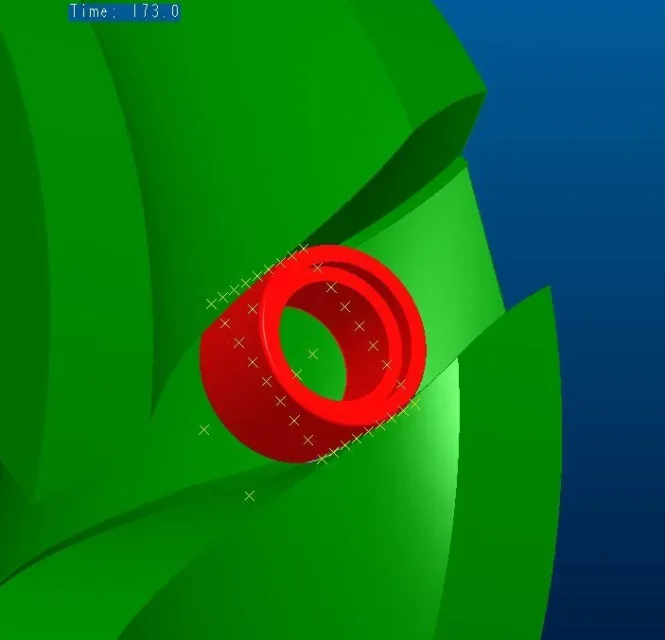
the cut was decent but there were points where I interlinked between cam and rollers; especially at the beginning and end of the cut (see attached pictures).

so I thought I had to turn the roller plane where I put the points for the trace curves. the situation improved, but the motion law I assigned to the roller plane was random: a sinusoidal law, like the main one of the tower, which in half reverses the direction (otherwise the cutting plan turns too much on itself).
but, what is the right movement law to assign to the roller cutting plane?

How would you do that?

would you tell me where I can find more detailed information about this type of 3d modeling?
I searched on the web, but I did not find anything except videos like what I attached in which, however, you can not see how to do.

Thank you.
Goodbye
 

Attachments

  • Rotoblock.zip
    Rotoblock.zip
    6.9 MB · Views: 26
  • 1.webp
    1.webp
    16.9 KB · Views: 27
  • 2.webp
    2.webp
    9.3 KB · Views: 145
  • 3.webp
    3.webp
    13.8 KB · Views: 146
are the classic globular cams that are on the rotating boards like those of filippets colombo. can be with cylindrical tooth mounted on bearings or swivel ovoidal. basically they are two normal gears that do not have the profile to evolve of circle but have the cylindrical shape.


just create the propeller with a sweep cut that maintains the correct tangency of the cut silhouette.


work a little as the cynical wheels only that depending on how they are built you have that at each turn you move a board division.

If I had to do this with solidworks, he coupled geometry and assigning an incoming engine generates me the law of movement of the table depending on the cam I design while ignoring the theory of forces or speed. you don't have a similar tool?
 
I have the same instrument and it's the proe mechanism module.
but to make the cut both with sweep and with the surfaces, I can not remove some points where the roller touches.
 
but to make the cut both with sweep and with the surfaces, I can not remove some points where the roller touches.
I think you are encapsulated in those geometry problems that you encounter on the 3d model when trying to replicate for example the excavation that generates a candle cut along a certain curvilinear path.
in the past were written a few hundred posts related to the helical excavation through sweep and the inconsistencies that emerge with the real excavation made by a mill.
 
I attach your modified file using the envelope movement.
Basically I stuck the cam you need to build and made him rotate around the support shaft of the roller (maintaining his movement too).
Now, not entering into mechanism, you have the function "motion analysis" that allows you to create a union of surfaces that delimite the volume occupied during the movement. I recommend, if this method can suit you, it brings the quality of invilusion creation to 10 (I left it to 8 to see if it worked) and select only the parts you want to include in the envelope (I put only the outside and the roller tree).
Once you have the surface you can use it to dig the cam.
 

Attachments

Hi.

I think you can't do it because the section of the roller used to track the curves on the cam is constantly parallel to p_lateral (I don't think anything alternative about it).
instead, taking into consideration the two tracked curves that define the position of the roller axis (in case they are not the correct ones you can always recreate)


you can on the points of these curves reproduce geometrically through cylindrical surfaces the roller.
the intersection curves of the new cylindrical surfaces (intersection between the previous cylinder and the next one) define exactly the two limit blends you want to get (rolling edges).
 
Sorry, guys, but I neglected the tread for a while.
I broke my mind and found the solution.
I posted it on forum ptc and is also discussed extensively with other people.
Hi.
 
Hi.
I was trying to prove the method you suggested, I downloaded it all but the aid goes wrong because it does not find the part:
cam_roto_pm2_1400

Could you train him?
Thank you.

bb
 
Hi.
I was trying to prove the method you suggested, I downloaded it all but the aid goes wrong because it does not find the part:
cam_roto_pm2_1400

Could you train him?
Thank you.

bb
... I was referring to the test aid_camma posted by luca1669
 
Sorry I have no way to recover the file now. did you try to download the zip in the first post?
...I tried to make changes to the envelope and told me to check the licenses...... but does it take a license in particular? ?

bb
 

Forum statistics

Threads
44,997
Messages
339,767
Members
4
Latest member
ibt

Members online

No members online now.
Back
Top