You are using an out of date browser. It may not display this or other websites correctly.
You should upgrade or use an alternative browser.
You should upgrade or use an alternative browser.
AlessandroC.
Guest
Hello emanuele,
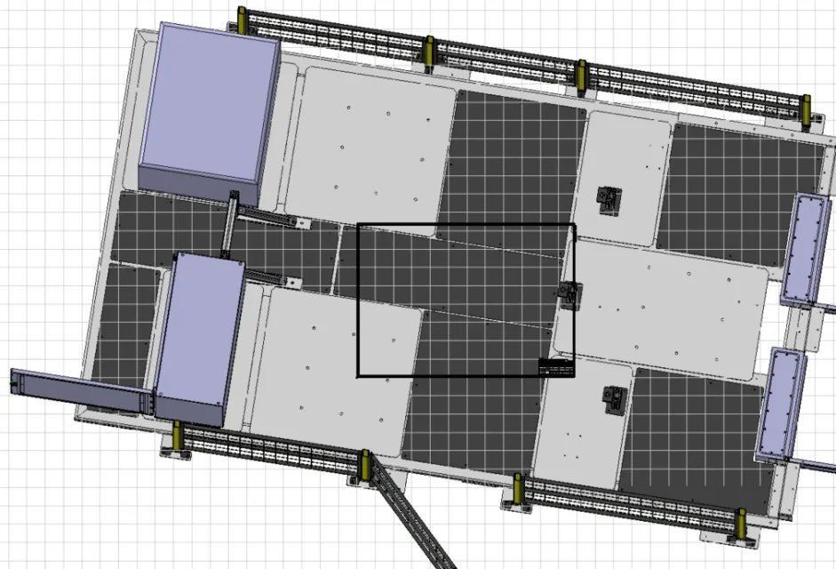
the axieme has its own spatial orientation (the one you see from the bottom right).
the first component you insert is automatically aligned to the inside of the axieme, but it can be freely moved/ruoted, if it is not isovincolato (I think it is your case).
When I find myself in your situation, I proceed as follows:
I hope I've been helpful
Hi.
the axieme has its own spatial orientation (the one you see from the bottom right).
the first component you insert is automatically aligned to the inside of the axieme, but it can be freely moved/ruoted, if it is not isovincolato (I think it is your case).
When I find myself in your situation, I proceed as follows:
- insert a new part into the axieme
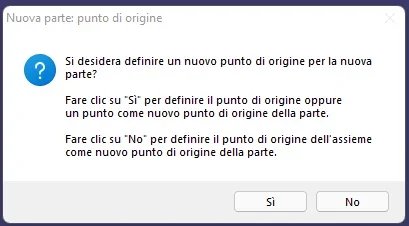
- to the message to define the point of origin click "no": In this way the new part is aligned to the reference terna of the axieme.
- block the new part
- align mine together with the new part (you need to understand which component to bind, even according to the components you have available)
- Optional: you can block a part of your set and delete the auxiliary part you created at point 1.
I hope I've been helpful
Hi.
falonef
Guest
But I'm a message when it looks exactly?Hello emanuele,
the axieme has its own spatial orientation (the one you see from the bottom right).
the first component you insert is automatically aligned to the inside of the axieme, but it can be freely moved/ruoted, if it is not isovincolato (I think it is your case).
When I find myself in your situation, I proceed as follows:There will also be other quicker methods, but at the moment I don't think of it.
- insert a new part into the axieme
- to the message to define the point of origin click "no": In this way the new part is aligned to the reference terna of the axieme.View attachment 65377
- block the new part
- align mine together with the new part (you need to understand which component to bind, even according to the components you have available)
- Optional: you can block a part of your set and delete the auxiliary part you created at point 1.
I hope I've been helpful
Hi.
because I don't remember seeing him yet di
emanuele grasso
Guest
I'll let you know.
emanuele grasso
Guest
beautiful method.. works
Thank you. @alessandroc.
Thank you. @alessandroc.
Vittorio
Guest
Vittorio
Guest
appears when you insert a new catpart into the catproductBut I'm a message when it looks exactly?
because I don't remember seeing him yet di
falonef
Guest
to me never appearsappears when you insert a new catpart into the catproduct
Vittorio
Guest
probably insert "existing component" and not "new part"to me never appears
falonef
Guest
I'll let you know
falonef
Guest
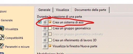
I don't have the message because we have activated the option in the settings to automatically create the axle system when creating a new catpart.
AlessandroC.
Guest
I read your answers now. . .
everything corrected what you wrote on the message.
everything corrected what you wrote on the message.
AlessandroC.
Guest
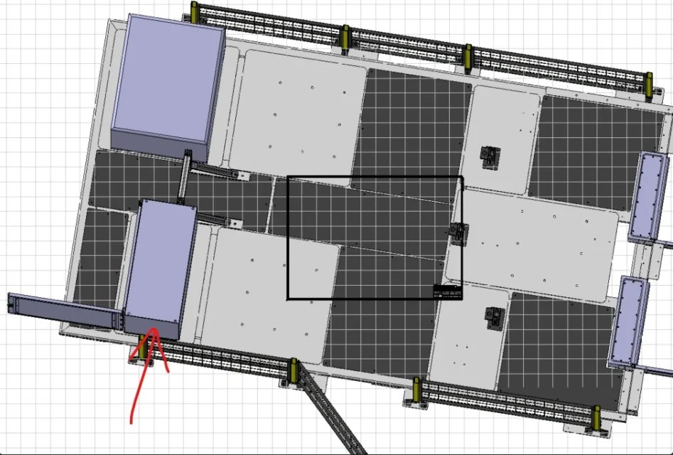
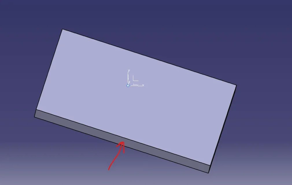
I am not very sure of this statement.If you just need to align so that it is orthogonal.. just click on the face I marked you with the red arrow
View attachment 65380
I agree with you, but a verification is always better to do it: we do not know a priori how that face is oriented to other components.
I have not even understood what the piece really is, they play in a very general way and I might be wrong:
Vittorio
Guest
it worksI am not very sure of this statement.
I agree with you, but a verification is always better to do it: we do not know a priori how that face is oriented to other components.
I have not even understood what the piece really is, they play in a very general way and I might be wrong:
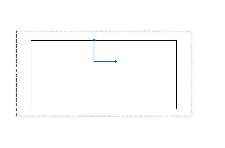
if you do a tilted catpart and click on the face indicated by the red arrow ... the view in the catdrawing becomes orthogonal to the face you selected for the table setting
However the right job is not that, but that of having a proper axe system
this could be a method to speed up the temporary solution
 That post @emanuele fat I feel like a plant of a shed
Last edited by a moderator:
AlessandroC.
Guest
on this no doubt! I often use your system too, because it is very quick.it works
if you do a tilted catpart and click on the face indicated by the red arrow ... the view in the catdrawing becomes orthogonal to the face you selected for the table setting
my consideration was not to have the certainty of orthogonality between the various parts of the piece, especially when the 3d model is not made by me.
that post of @emanuele fat seems to me a plant of a shed
falonef
Guest
Here are the options I set. I don't have the messageView attachment 65404if you refer to this flag .. the question of post #2 does it anyway
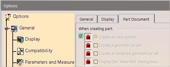 I insert a new non-existent part. nessumessaggio appears.
the new part created on the fly has the axle system.
but no message.
AlessandroC.
Guest
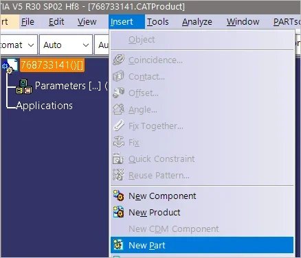
I think it's a "command" problem.I insert a new non-existent part. nessumessaggio appears.
the new part created on the fly has the axle system.
but no message.View attachment 65419
from the menu insert->new part should not appear the message.
if you use the command from the toolbar (see image below), what happens?
to me the message appears only in this second case

falonef
Guest
This way I have the message.I think it's a "command" problem.
from the menu insert->new part should not appear the message.
if you use the command from the toolbar (see image below), what happens?
to me the message appears only in this second caseView attachment 65420
but I tested with custom settings.
If instead I refer to the original ds settings I can reproduce what you have said with the automatic creation option of the active axle terna.
so in my settings there is some other option to adapt
ps: test with r30
AlessandroC.
Guest
I only checked with the old version r24-.This way I have the message.
but I tested with custom settings.
If instead I refer to the original ds settings I can reproduce what you have said with the automatic creation option of the active axle terna.
so in my settings there is some other option to adapt
ps: test with r30
you probably need to check something in personalizations from management, but I don't know where to put hands for this
Forum statistics

