• This forum is the machine-generated translation of www.cad3d.it/forum1 - the Italian design community. Several terms are not translated correctly.

problem tangenza superfici

  • Thread starter Thread starter Sokak
  • Start date Start date

Sokak

Guest
Good morning, I'm colliding with a problem I don't know how to solve.
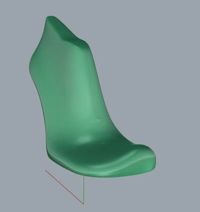
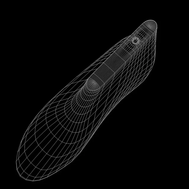
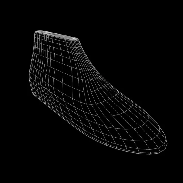
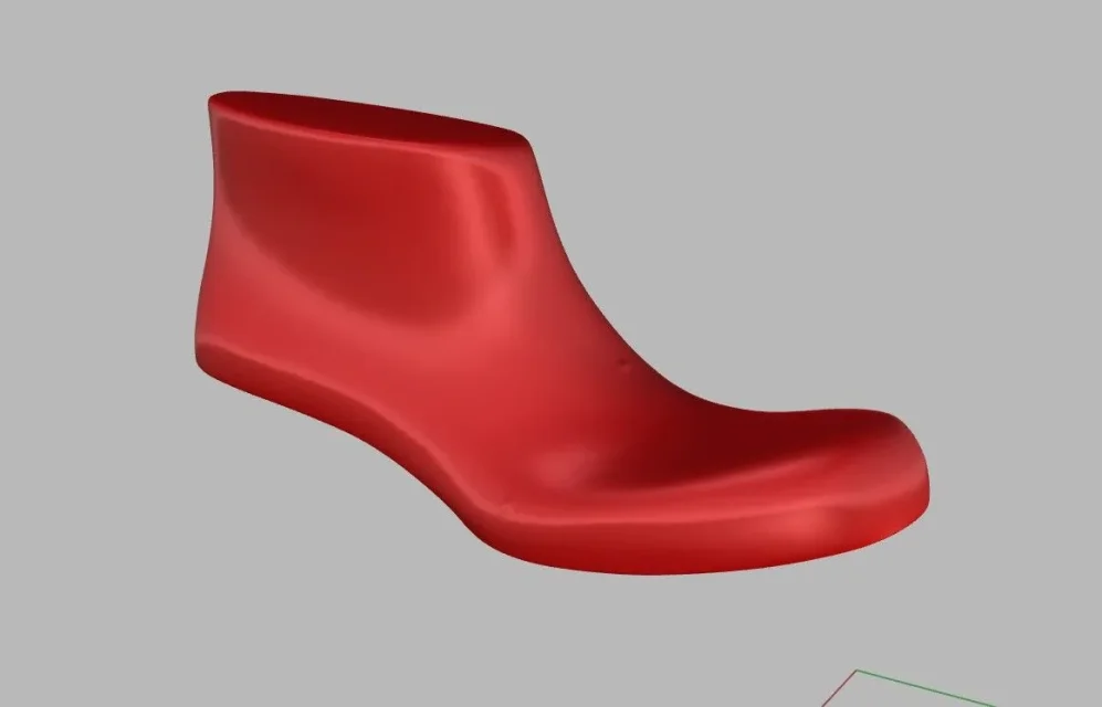
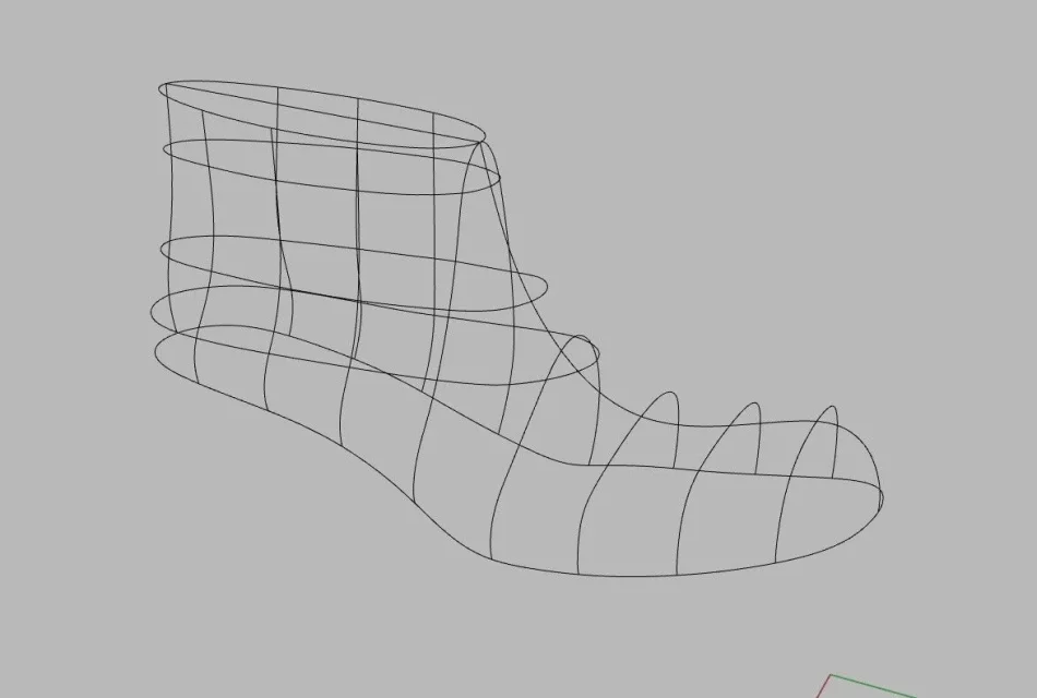
I have a stl file of a shoe shape. from this starting mesh I create the skeleton of curves that I will need then to generate the surfaces. It is important that the surface passes through those curves (which are intersections on mesh) so both as adjacent as possible to the base form.
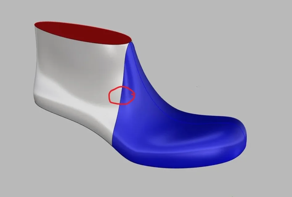
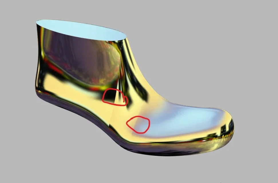
with the network curved command the result is quite good but not optimal, but more important is that I have to create multiple separate surfaces. this makes that once you create all the surfaces, these are not in tangence among themselves, generating well visible steps and discontinuities.
I would like to ask how this problem could be solved.
 

Attachments

  • 01.webp
    01.webp
    13.5 KB · Views: 17
  • 02.webp
    02.webp
    32 KB · Views: 20
  • 03.webp
    03.webp
    17.3 KB · Views: 20
  • 04.webp
    04.webp
    30.1 KB · Views: 24
hi, I press that I do not use rhino, but I make models and molds for footwear since 2002

with the cad that I use, in these cases, once arrived to these two surfaces that are not tangent you cut off a part of edge from both surfaces (not too little, not too obviously) and you create a tangent surface to the other two, starting from the curves created by the cut edges of these last surfaces, so that you feel the tangency. I'll tell you why you might have this chance, too.

another solution could be to get the curves in different places

otherwise I know that there are plug-ins to reverse, when they start working also for these things please tell me;)
 
It's a bit that I don't use rhino, if I don't remember badly you can set the tangence between adjacent surfaces, but you may have problems in the vertices and the adaptation of surfaces
 
Thank you both. effectively there is the possibility, which I have already tested, to cut part of both surfaces and then use a match between the two. the problem however as highlighted is that the command fails to properly manage the vertices and the result is bad.
 
Thank you both. effectively there is the possibility, which I have already tested, to cut part of both surfaces and then use a match between the two. the problem however as highlighted is that the command fails to properly manage the vertices and the result is bad.
if you try to make less surfaces giving as curves passing those inside? I don't know what can come out, you should go for attempts...
 
is it possible to have the stl file to see if there are extra vertices (i.e. the adjacent vertices the 2 surfaces, which should be those that determine the inconveniences you speak about)?
 
I can't convert the 3dm. I tried to convert it online but it always gives me error.
you should post the file in obj format.
I thought the problem was in the slate for this reason I wanted to take a look at him. instead now I understand that it depends on the tangence of the surfaces.
mail equally the obj, however so that I can open it with 3ds max
 
I am not a magician of the surfaces but something I have done (buckles of armchairs); I remember that the first thing that taught me the instructor was that we call it surface modeling but it is not correct to call it that, because in reality it should call itself curve modeling. I didn't use rhino but it seems obvious that your curve mesh construction strategy is wrong. In that way you are forced to make 2 distinct surfaces that is evident they will never mate in continuity of tangency. I found a mesh tutorial that seems to me right in your case, even if it starts from a stl that will result from a reverse engineering. but I think it's still useful to set up a new strategy.
 
Good morning, I'm colliding with a problem I don't know how to solve.
If you make separate surfaces, in the second you have to set tangency on the edge of the first. If you don't tell him, how does the software know your intentions?
the network works well, but when it doesn't work you have to change strategy and use other types of surfaces (rail, square, etc.). even because if you increase too the degree of a surface, this then begins to make unwanted oscillations (phenomenon runge-kutta)
with the cad that I use, in these cases, once arrived to these two surfaces that are not tangent you cut off a part of edge from both surfaces (not too little, not too obviously) and you create a tangent surface to the other two, starting from the curves created by the cut edges of these last surfaces, so that you feel the tangency. I'll tell you why you might have this chance, too.
What a horror!
this technique is known as "blend cordle" or "string chord" and is used for precise purposes of style, not to allow to agree two surfaces that fight.
 
Last edited by a moderator:
I saw the video and the procedure is clear but it's not what it does to my case. I would have used it if I could.
the problem arises when, for example, you have a form of departure with strong asymmetrics. in that case those curves used in the video do not guarantee a control of the surface so as to approach the model of departure.
for this reason I decided to use control curves that were perpendicular to the shape so as to have a greater control, but obviously at the expense of having to generate more surfaces to be put into tangency.
 

Attachments

  • 05.webp
    05.webp
    8.5 KB · Views: 16
If you make separate surfaces, in the second you have to set tangency on the edge of the first. If you don't tell him, how does the software know your intentions?
the network works well, but when it doesn't work you have to change strategy and use other types of surfaces (rail, square, etc.). even because if you increase too the degree of a surface, this then begins to make unwanted oscillations (phenomenon runge-kutta)
In fact I set the tangency as you say, but how does the software manage that type of vertices? in fact the result is bad.
 
In fact, the initial approach of the video is not quite convincing. but there are too many "hand" adjustments of the splines.
at this point it would be better to make horizontal sections (with possibly other vertical ones) and then to extract the edges, if you just want to get a solid as much as correspondent to the stl. i.e. to take the stl mesh, to dissect it and to extract the edges.

For example, in the photos below, only horizontal sections would be sufficient to define a satisfactory cage. Each horizontal line could be considered a horizontal section of the initial slate, to overcome tangency problems, it would be enough to make more sections where the mesh needs it.
 

Attachments

  • _2.webp
    _2.webp
    108.8 KB · Views: 13
  • _1.webp
    _1.webp
    72.3 KB · Views: 14
What a horror!
this technique is known as "blend cordle" or "string chord" and is used for precise purposes of style, not to allow to agree two surfaces that fight.
Maybe with rhino comes a drunk, or even no... I ask vein o_o I have specified that I do not know the software, but with powershape if the starting surfaces are good and cuts in the right place the connection is good. This technique I use so much, among other things the default surfaces are tangent, you are the one who should turn off the tangency.

I said this... I gladly follow the discussion!
 
the two surfaces as in #1 are built too differently to achieve a sufficiently smooth conjunction. the strategy of the video in #10 is more correct, however to recalculate a form in an acceptable way would need more "pick".
I follow with interest.
 
It's in Spanish, though.
at the beginning of the video makes an adjustment of the surfaces that present wrinkles (he calls them wrinkles, but I think it is the same problem encountered by sokas
 

Forum statistics

Threads
44,997
Messages
339,767
Members
4
Latest member
ibt

Members online

No members online now.
Back
Top