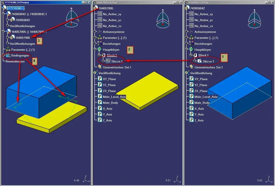
• This forum is the machine-generated translation of www.cad3d.it/forum1 - the Italian design community. Several terms are not translated correctly.

problems during the sketch phase in the environment product catia v5

  • Thread starter Thread starter 9simo0
  • Start date Start date
I did as follows:
1. created a catpart.a
2. created a catpart.b and copied the catpart.a sketcher with paste copy with connection
3. created a catproduct and inserted catpart.a + catpart.b
4. created positioning constraints

It's okay!

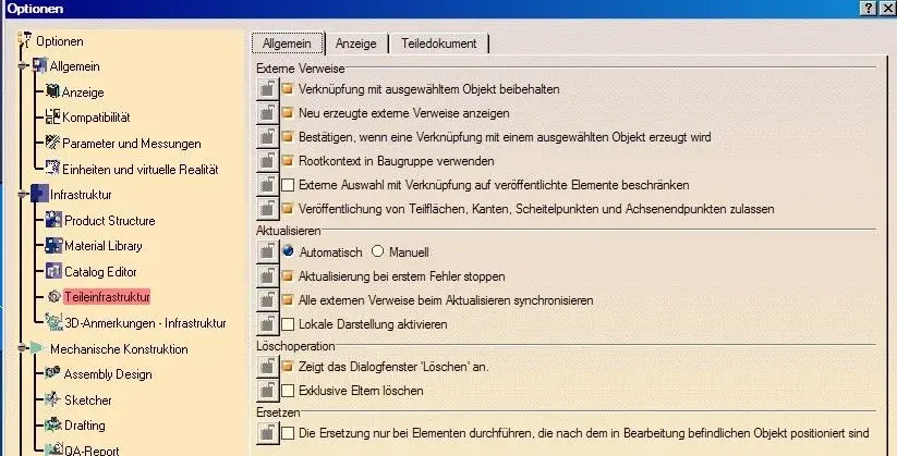
also here are my settings

ps: if you copy and paste a catpart.a sketcher to catpart.b directly into the catproduct create a context (the component symbol changes wheel color = green with horizontal chain and then you can not move the catpart.b sketcher as you wish

the use of the context can be very practical: for example in our case in the construction of clock movements with the various concatenations of the individual components.

"sooooooooooooooooooooooooooooooooooooooooooooooooooooooooooooooooooooooooooooooooooooooooooooooooooooooooooooooooooooooooooooooooooooooooooooooooooooooooooooooooooooooooooooooooooooooooooooooooooooooooooooooooooooooooooooooooooooooooooooooooooooooooooooooo
 

Attachments

  • context_01.webp
    context_01.webp
    132.2 KB · Views: 23
  • context_02.webp
    context_02.webp
    67.6 KB · Views: 16
Yes, that operation I knew how to do it. ..but it is not always helpful...for 2 reasons:
1) you have to give a reference to the sketch...and you are not always in situations so facilitated to give it because where the cat can not be useful to you;
2) if you work with strange geometries wrapped the points you need are not exactly the ones of the sketch...I don't know if I explained... and then it is always useful to give references to the flight with other part without going to look for here and 200,000 sketches. ..even because wrapped when you have complicated assemblies to go to find sketches really becomes a company:frown:
and I add a third reason... if I for any reason have to refer to a chord created in the body and not in the sketch. You get a little complicated, don't you think? eheh
with regard to the problem of moving the part within the product, just isolate the sketch once you have finished working :smile:
Hi.
 
Okay, but then put an example so maybe we can figure out more.
I thought you were stuck, so I invested time to help you.
 
Excuse me. But I had previously written that I had solved the problem... I followed the advice of mcbramby... I said that you really lost time:frown:
 
Excuse me. But I had previously written that I had solved the problem... I followed the advice of mcbramby... I said that you really lost time:frown:
rereading the forum seems very strange to me that the system does not work, the only doubt that comes to me and that you are trying to relate two non-compatible geometries (e.g. to place an adistence between the line of your sketch and a geometrieternal that is derived from a spline that can seem linear).
another doubt may be that you have not been able to update the geometry automatically or in the environment.

Hi.
 
Hi.
no I ferrezio the update automatically I active it and then the problem also concerns the projection of edges or points of a part geometry...they are things that normally should do...cmq the problem I solved by remaking catsetting to the cat.
thanks for the interest,
Hi.
 
I found out perhaps the real reason for my problem....practically after an hour of investigation I came to the conclusion that my problem was at the tip of the item "to preserve connection with the selected object". If I'm pointing out that voice, it's okay.
Of course, I will only give it up and only in cases where the reference makes me extremely necessary! because without a colleague it is a good problem:
Thank you all! :smile:
 

Attachments

  • COLPEVOLE.webp
    COLPEVOLE.webp
    15.4 KB · Views: 20
I found out perhaps the real reason for my problem....practically after an hour of investigation I came to the conclusion that my problem was at the tip of the item "to preserve connection with the selected object". If I'm pointing out that voice, it's okay.
Of course, I will only give it up and only in cases where the reference makes me extremely necessary! because without a colleague it is a good problem:
Thank you all! :smile:
I'm sorry. do you read the messages? It was the first thing I had reported to you!

Hi.
 
I invite you to reread everything because I read the messages... but maybe you missed my last message...that is, I think you read it well...you wrote me to point that voice...in fact I had already bet it, but if you read my last mess I wrote that my problem was just that...in fact I thanked you...
Hi.
 
far from me to raise controversy... I'm interested in the case because it's really messed up and I'd like to understand something.
It seems strange to me that the problem is linked to the activation or deactivation of the option, but there must be something different.
because if you tell me what you want to model in a contextual way you have to activate the option.
so I still have two potentials to this.
Sometimes you have to pay attention to the selection filters, I happened that some users involuntarily thought to call the point function, instead they activated the point filter, so for the subsequent actions it was not possible to select other objects outside the point.
then verify its bar
or, and often can happen, it is due to a malfunction of the video card drives (especially after the screen saver is activated), if this is not professional.
and this malfunction sometimes restores with the simple exit from the sketch environment.

Let me know I'm curious.

Hi.
 
Then I try to explain myself better because surely my fault is that I can't explain myself:
We start from the beginning...it is less than six months that I use the catia, I did the course with a boy inside the company who had made the official course.. In these six months I took care of some work and I realized that often and gladly the catia made me a bad joke...i.i. I make you an example so maybe it is easier to explain to you the problem...
my last work was to design an avionic box...this box had to be disassembled in 6 pieces...the cap, the bottom and the other 4 walls. First I drew all the pieces without holes... then I made the holes on the central body. So I had nothing left to do but to do the holes both on the plug and on the bottom... on the plug everything ok... but when I went to do the holes on the bottom there was an unexpected...that is... I entered the part and I did a sketch then I wanted to create points and give these points a concentric bond with the holes of the other 4 parts. But when I select the point and the edge of the hole and then I opened the window to give the bond, it was as if the hole I wanted to give the bond didn't really exist! :frown: not only...if I select the edge of the hole or any other geometry of that part and made the projection on my sketch plan, it didn't make me! I'll tell you more...would it happen to me that if I select maybe the point and the hole to give the concentricity to the point, and I opened the window to give the bond...the caia closed me!!! t.t then what do I do... usually first save... and if for some reason I can't save, first I try to make a projection of some element of that part on the plane of my sketch... if it suits me otherwise it means that it won't even give me the bond...
in these last days I understood how to reach the problem...i.e....I noticed that if I remove the saying that famous to preserve the connection, everything goes normal (it is to say why in reality it is not at all!) as it should be because the catia creates as its reference a geometry "dead" thus losing every connection...
Now..you could tell me...”but why don’t you use the features to make holes in multiple parts? ”
But if the holes are different in diameter...? and then...this was an example but I might need to give references not only for holes but for any other reason...I for now managed to solve everything by popping up that voice...but if I needed to keep the links I wouldn't know how to do...
As for the video card drive I don't know... I'm not so sure... for 3 reasons...
1) this joke does not do it with all parts but only with some parts in particular;
2) this joke also does to the boy who did the course to me and we have 2 different computers
3) I tried to open the product with my personal laptop...understood less than a month ago...and I do it with that...
So I don't know what this problem might be about...:frown:
I hope to have explained well eheh if you have in mind some possible you have only to tell me so I try andhehehe thank you very much for the attention.
Bye-bye!
 
in caia the links are monodirectional, i.e. if the "parta" receives a link (external reference, parameter, formula etc.) from the "parteb" then it will not be possible that the "parteb" receives one from the "parta".
the problem would lead to this.
 
in caia the links are monodirectional, i.e. if the "parta" receives a link (external reference, parameter, formula etc.) from the "parteb" then it will not be possible that the "parteb" receives one from the "parta".
the problem would lead to this.
That's the problem.
If you want to create dependencies one to many you have to introduce a part in the axieme that contains all the references to which all the other parts are supported.

Hi.
 
I'm a little lost. I figured out what you want to tell me, but I didn't understand how to act.
I mean...if I understand correctly...if I refer an element of the part to an element of the part b, then can I not refer an element of the part b to an element of the part a????? :frown: but if it was necessary to do it as I do? :frown:
thanks to all for the help :smile:
you have to introduce a pate c that has no solid geometry but only wire-frame (points flat lines etc.), so instead of pointing to up b, you have to point to up c and b on c.

or use the features together, so you can also make different holes on the various parts, just assign the "hole series" in the main panel that opens with the command.
Hi.
 
I'm trying to see this solution, but it's not like I'm getting back so much. I'm not saying it works. I'm just saying that I have to find a way to handle the parts in this way... i.e....if I have to project a part edge b on a part plan a, but I have previously given a reference in the opposite direction, I can, but how do I put in the middle part c? Let me try again, if I can tell you that I'll break the boxes.
geazie thousand for help:smile:
 
I think I can understand the mechanism! eheh
in a product there must be a part that takes references of all the others!
is a bit like in Italy....there are those who are forced to take it only and only in that place and there is who is destined to put it just! !
Sorry for the comparison but it came from my heart!!!:biggrin:
thank you all for the help you were very kind all! :smile::smile::smile:
 

Forum statistics

Threads
44,997
Messages
339,767
Members
4
Latest member
ibt

Members online

No members online now.
Back
Top