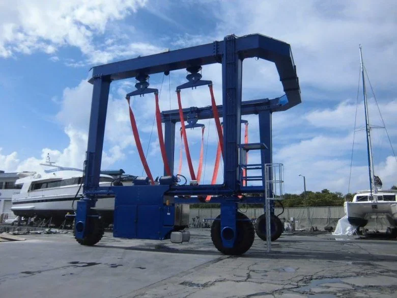
Hi, everybody, my name is alessio.
I am a mechanical engineering student at the faculty of firenze. I was assigned a project of construction of machines that previews the sizing of a motorboat for boats. I find myself in difficulty because after fixing maximum dimensions and technical specifications I did not receive much information to proceed correctly.
I started studying the structure of beams, but I have problems understanding the correct setting of the project. the professor says to neglect in the calculation the dot that connects the two side "faces" and then possibly verify if this assumption was correct with a software, but I do not know which to use it.
If there was someone who could direct me on a road to follow or who has already found himself making the project of a similar lifting device, I would be very helpful.
p.s. attach generic photo of the object
thanks, greetings
alessness
View attachment 43401
It's gonna be late, but maybe it can be helpful to someone in the future.
I'd come this way
first step
1) I consider the machine made up of two flat frames (transferring the summit traverse)
2) flat frame bound in "simple support". (Being on wheels one will be braked and the other not. or at most if both free. the minimum deformation, given the presence of the lower thief in correspondence of the cart, is divided equally on the two wheels)
2a) in the case of two wheels brake/locked with wedge frame hinge
3)Download with weight forces distributed on the rods and vertical components of the two inclined reactions (in space) that give the straps. the thermal action the transscureri seen hopes the boat will not remain weighted for weeks, while for the wind I would make a calculation to turn aside
4) Solve the frame (the choice if to hinge or frame the knots of the bottom or for higher absurdity, are to be made in relation to the type of connection provided)
5) certain stresses occur resistance and stability (point load of the pillars and flexotorsional shifting the upper traverse) frame rods
second step
6) the horizontal components of the straps pull cause torsion in the mounts, bending off the top traverse (sollecitation to be added to the previous ones in the checks) as well as a state of constant compression effort and bending (pairs at the ends) for the dot that unites the two flat frames
6a) verification of the previously dimensioned sections with also new stresses
7)verification of resistance and instability
8) verification of connections (welded or bolted that are) through classic analytical methods and sizing of pin bolts and welded cords
third step
9) fem modeling of a space frame through beam elements, application of loads and control of results (the manual calculations should not be much different. rigidity between flat frames and dots may vary the stresses on this last and torsion in the mounts)
10) test rods with model stresses
11) check links with model stresses
fourth step
12)substructure of the model by inserting portions shaped to plate/shell elements, in order to grasp the real distribution of the efforts in the plates and the links
13) extrapolation of model portions (restoring boundary conditions with stresses present in the "cut" points) for any detail studies modeling welds and bolts with all pharmacopoeia of possible imaginable links
14) any fatigue analysis of the components (being a mechanical object can be interesting to do so, but it is not my specific field)
fifth step
15) tipping test for wind gust that hangs on the suspended boat. it can be simplified all considering the surface on which hangs the wind a parallepiped that envelops the boat, and consider all the machine infinitely rigid. It is a simple tipping of a rigid body (analogue to the supporting walls designed "the old way"), to determine therefore stabilizing moment, tipping moment and the safety coefficient between the two


