• This forum is the machine-generated translation of www.cad3d.it/forum1 - the Italian design community. Several terms are not translated correctly.

raccordo in lamiera

Olan

Guest
hi, I have a problem, I had created a discussion about industrial design and I would not want to create doubles but the question is now specific to solidworks then. .
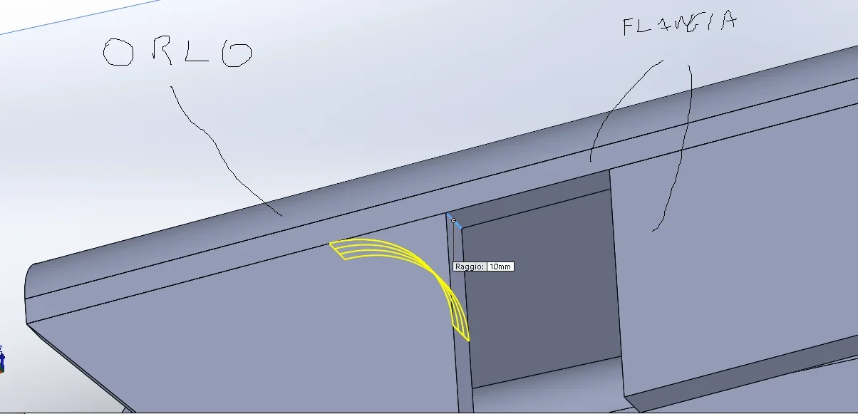
I have to create a fitting sheet (see attached picture) how can I do it? the result is that in the photo.
created the sheet metal I must then bend it into the ends and "bomb" in the center presumably with a forming instrument. .

going by step I guess you have to use "full with loft" but I just don't get it. .
lamiera raccordo.webp
raccordo da fare.webpThank you.
 
following the directions of the post I arrived at this point... and now? How do I convert this to sheet metal?
esterno.webp
interno.webp
 
I don't know which version of sw you have (you should update your profile) but the result could be this:
01.webp02.webp
 

Attachments

Thanks mike, I also take advantage of it to explain what I have to do because I have some confused ideas. I hope you can help me. to the chord you see I have to add a "bomb" (where indicated in photo) and a crush on the vertices. the model must then pass to the professional who will create the mold. the second part of the work consists in switching to the professional who deals with cutting the sheet the development. starting from the fact that I have to get to development I am trying to build everything as a sheet. Am I okay? I can't pass the model with those cuts.

use solidworks 2012
 
hi alberto, could you explain to me step by step the procedure to transform the model in sheet metal and then to reach the development in plant? I'm reading the various tutorials but I can't..even if I still have the doubt of being on the right path.. .I don't see how it can get to do the bombing by a result like this... not to mention the fact that the development of the sheet just serves me to have idea what development has the piece...in reality then the connection is obtained from the molding of a sheet of sheet having x and y quotas that will depend on the development itself. I don't know if I could explain. .

...will also arrive this course of solidworks..
I'll coach you this sheet metal tutorial, which I flew this morning, waiting for the prole to wake up:wink:View attachment esercizio solidworks lamiera.pdf
 
Thank you very much! In the meantime this is what I managed to do.. is a solid but not a sheet, if I can make the bombing to the professional for the mold I can give this model... then to that of the sheet I find the development as you indicate me too. I read then that on solidworks 15 it seems possible to find the development directly from the surface. . .
Raccordo con alette.webp
 
if you need the development from the "raw mode" surface then throw away solidworks and adopt a rhino.
http://www.rhino3d.com/it/:

I add to the discussion and I take advantage of it to thank tree for its excellent mini-tutorial.

Good boy!
 
Good evening,
I have a problem.
I should realize the chord in the figure or rather the program gives me the connection in figure that in fact is not what I want.
It's like he gave it backwards.
suggestions?

Thank you very much to all.
 

Attachments

  • Immagine.webp
    Immagine.webp
    29.3 KB · Views: 0
That's because you didn't join the two bodies. therefore the fitting, which can be done only on a single body, is done on the edge of the triangular piece and not on the edge of the wound.
try to hide the triangular body on which the connection occurs; If the rest disappears I said a cabbage, otherwise you took a false step in modeling.
but in the company Is there anyone who knows how to use this damn software that teaches you something?
Thank you 1000.
I can see what I can do in the morning.

ps are right you are separate bodies.
The false step I did.
I have to understand where:)

Thank you
 
you didn't put the tick on some side result, probably on the extrusion of the triangular piece
 
you didn't put the tick on some side result, probably on the extrusion of the triangular piece
the problem is as follows: the common sense would suggest doing that extrusion (or extrusions) with the appropriate functions (base extrusions, extruded cut, extrusion in revolution, ect ect); In reality the final scpo is to have a sheet in which the flattened mode in draft is guaranteed.

I have noticed that, for example, if I use a base flange (or a flange with sweep so much to say) on the one hand, not only does it not give me for example that connection (which would give me if I used the canonical functions) but it does not even give me the flat repetition in draft.

vice versa if I use the canonical functions I can realize that fitting but it does not make me flat repetition (or mrloo me does it until I use functions like extrusions or canonical cuts).

Perhaps it will be that I have not penetrated the logical sheet but if I have complex geometries the sheet (flatten version) goes definitely in tilt.
 
I don't understand what you can mess with every time. . .
instead of using edge and flange commands, as in my example, the edge flange command as I told you. And then you cut.

of course on how models, where there may be problems you know only since from an immaginena you get out very little.

now part of the pips
to understand; I like to find solutions, tones my ego, but to guess and put 30 posts, repeating the same things and passing from one thread to another as to the fish market, to understand what the hell you are doing on spondines of a thermonuclearegobale to an office where no one is able to use a software that paid fior of money and you are at the mercy of yourself, frankly begins to annoy me. If one does not know how to do a job and is practicing it must be explained on site, discussing in real time, how to do things. If they don't know how to explain them, they send them out to make the economy run. if instead you are a regular paid employee and you have mired knowledge that you do not possess you are simply stealing the salary (and the time of others)
make your considerations and give yourself a straightened
 

Forum statistics

Threads
44,997
Messages
339,767
Members
4
Latest member
ibt

Members online

No members online now.
Back
Top