• This forum is the machine-generated translation of www.cad3d.it/forum1 - the Italian design community. Several terms are not translated correctly.

reticular structure analysis in ansys

Utente cancellato 92203

Guest
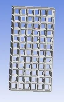
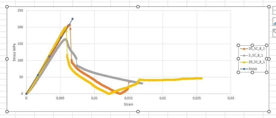
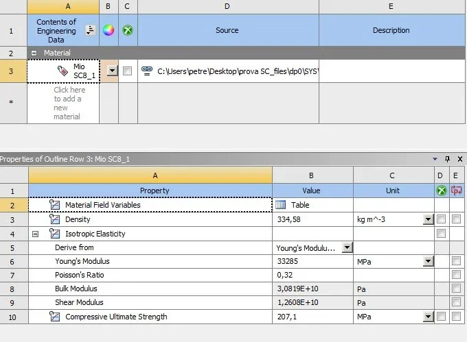
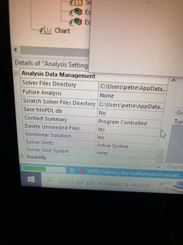
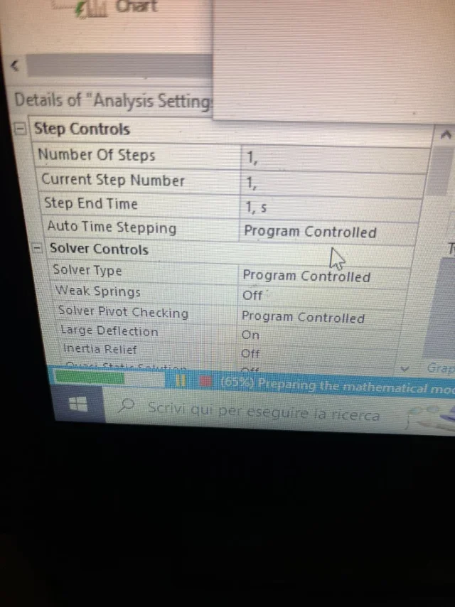
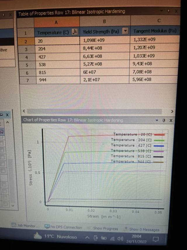
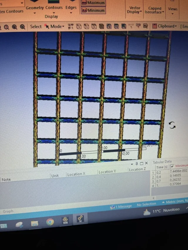
Hello, everyone. I ask you for help because I have to make on ansys a model that simulates the results found in the laboratory on trials that have a " latex" structure. the material in question is a ti6al4v alloy. 3d was created with solidworks. inserting the various parameters derived from the real curve my test on ansys exceeds the breaking voltage (blue line in the image with 4 experimental curves), how come? Where should I intervene? thanks in advance
 

Attachments

  • 2.webp
    2.webp
    15.8 KB · Views: 26
  • 3.webp
    3.webp
    16.8 KB · Views: 23
  • 1.webp
    1.webp
    32.8 KB · Views: 21
Bye. probably the section where you had to post ansys.

returning to the technical case, let us guess things....
if you get the results in blue with any fem is because you are setting a linear analysis in purely elastic field. If you want to see the blue curve precipitate you have to do a non-linear simulation considering the material with elasto-plastic characteristics.

but this is the basis for making structural anal of any type. If you want, look at the forum we talked about several times and there are examples made with freecad with the fem module of calculix.

if the material is incrude no longer has the linear behavior of the elastic field and therefore, increasing the definitions get a lowering of tensions.
 
I thank you for the answer and apologize for the wrong section, the fact of setting up an elastic linear studio I know I wanted to know why by setting a break sigma he continues to behave elastically beyond that value, at least it should give me error.
 
quoting what is said by @meccanicamg , ansys continues to give you the result of tension even for values far beyond yielding or breaking because it is a linear analysis and not affected by the actual behavior of the material.
Usually when you exceed the yield limit of the material should exit an alert, a sort of small pop-up in the lower part, but it does not block the simulation.
 
the fact that you have set one elastic linear study I know I wanted to know why by setting a break-up sigma he continues to behave elastically beyond that value, at least it should give me error.
You answered yourself. "breaking" is a plastic phenomenon. when you in ansys choose to make an elastic linear simulation, the software chooses a mathematical method that does not contemplate great deformations and other non-linearities.
Then you can write the parameters in the material tab. the software will transcur those who do not need for the mathematical method you asked him to perform.
 
ok thanks to everyone for the answers, but how do I impose this analysis not linear practically speaking?
 
then I go to memory:

first of all in the definition of the material you have to create a curve in which you see the ribbing and breaking, like the bilinear curves.. you can choose it in the left menu at the plasticity section;
after which you start a static structural, but in the list of passages left between the mesh and the loads there should be a voice like “analysis settings”;
there are all a number of options to activate the non-linearity that I don’t remember right now, but there will be a “large deflections” voice that you have to put on
 
I have already set large deflection on “on” and not linear solition “on” but always behaves linearly. Moreover, as you can see from the attached photos, the ansys library already shows all the characteristics of the material. so it would be ready for a non-linear analysis. I have attached you the behaviour of the structure, where you can clearly see that the rods do not undergo a slight decrease. I don't know.
 

Attachments

  • image.webp
    image.webp
    230 KB · Views: 15
  • image.webp
    image.webp
    164.3 KB · Views: 11
  • image.webp
    image.webp
    237 KB · Views: 12
  • image.webp
    image.webp
    259.7 KB · Views: 17
Last edited by a moderator:
if you have everything and if you are doing nonlinear analysis using the plastic elasto model can be poorly bound.
 
if you have everything and if you are doing nonlinear analysis using the plastic elasto model can be poorly bound.
As I am simulating a simple compression test, I set a shift on the upper face and a bond called “only compression support” on the lower face. It should be very simple but I don't understand why
 
going to memory if you do a non-linear analysis you can't set it with 1 step only, you have to tell him to do it in n step so that he divides the load you set for n step and cyclically calculates the deformed to step n with which he defines the new rigidities of the system to which to apply step n+1. so doing the system will correctly simulate the plastic behavior of the material.
 
quoto f_ingrasciotta. I have not used ansys for a long time, but now that he has spoken of it, I think that there is also this aspect here to consider.
in practice the application of the load cannot be instantaneous as in the classical static structural
 
I thank you very much for the answers, in the afternoon I do some tests and I give you feedback
 
If you go look lo studio plastic elasto of this spring made with thin saucer, you will see what has been done/set with a free program, calculix. As I told you, it was imposed on the computer to follow the sigma/epsilon curve of the actual or experimental material (I guess the true or presumed curves of a given material). Then a certain force was applied to see the deformation you get. clearly something will plasticize.
I don't understand why you have to apply the load step by step. If a structure is loaded with a certain force, that will go to download on the frames and then something will happen. If it is inside the normal parameters you will have deformations.... if too excessive you will have collapse.
ciao @meccanicamg, in non-linear analysis it is usually stepped up because the system, at the end of each step, calculates the deformation of the body under that certain load fraction and defines the new matrix of stiffness. of course in 1 step such consideration you lose.
 
I don't understand why you have to apply the load step by step. If a structure is loaded with a certain force, that will go to download on the frames and then something will happen. If it is inside the normal parameters you will have deformations.... if too excessive you will have collapse.
see it from a mathematical point of view.

in linear analysis, deformations are calculated as:

u = f/k, where f is the force vector and k the rigidity matrix of the structure that will depend on geometry, material and constraints.

if the analysis is non-linear, because for example the possibility of the material being able to yield is introduced, the matrix of rigidity becomes in turn function of the parameter that I would like to calculate:

u = f/k(u)

and then to calculate u I have to divide my vector f for my matrix k function of u .. but how do I know how much my k(u is worth), if I have not yet calculated u ..? you must by force pass for a time step analysis starting from the undeformed condition.
A stuff like this:

u1 = f1/k(u)
. .
u2 = f2/k(u)

etc.
Okay, but then operationally with a fem, why do you launch a single analysis? I don't usually see progressive steps in solutions. then, always operationally, I cannot charge a deformed structure partially because I should have a deformed 3d model to load again. so the thing is done only through numerical and matrical analysis.
for example with solidworks and its premium fem module (used just and years ago) and also with calculix, I don't see any more step but always one.
or better... there is a time of loading of the analysis in several seconds ...it is done the recalculation of the matrices, but in the end the result is only one.
more or less is the help part qui.
here is where the magagna is....often it is a parameter not in view of the time of loading of the structure.
 
Last edited:
hello petrelli92, hello mechanicalmg.
I have examined the characteristics of the material and found this data
- yield voltage 8700 kg/cm2
- breaking voltage 9200 kg/cm2
it comes that an elastic-linear analysis is more than correct because the incrudiment is small.
an elastic analysis only provides the tensions of the material. the verification must be done separately according to the reference norms and safety coefficients. the program should not give any "alert".
The problem lies in the model.
linear analysis can be made with models made up of rods such as the roofs of civil constructions, or linear analysis can be made with mechanical models.
the correct modeling is the frame consisting of rods where the program provides the stresses of each rod. then the tensions are calculated in the section.
mechanical modeling is not correct because tensions on mechanical elements, highlight the concentrations of effort in the singular points of the structure, i.e. in the edges and corners.
in those places tensions go to the stars.
therefore verify a structure according to the color of a very limited area of the volumical structure is incorrect and little significant.
On the other hand, checking the structure according to the efforts in auctions is more consistent with reality, although information on the concentration of efforts in the singular areas is lost.
Anyway, we civil engineers do this.
I hope I've been clear.
Hello everyone
 

Forum statistics

Threads
44,997
Messages
339,767
Members
4
Latest member
ibt

Members online

No members online now.
Back
Top