• This forum is the machine-generated translation of www.cad3d.it/forum1 - the Italian design community. Several terms are not translated correctly.

reticular structure analysis in ansys

wow excellent explanation, so you recommend me to create a structure consisting of simple lines that however have certain properties? like the diameter for example? Can I find some guides or videos? Thank you.
 
I didn't really think about it, but use the "trave model" which is to use not the solid shape of the beam but the section property. . ..can lead to what you would do by hand calculating rods and dots.
 
I am pleased that we agree, besides calculating frame is easier.
the properties of the rods are: area, inertia and elastic module.
almost all civil engineering programs have a trial period for evaluation without requiring purchase.
choose a program, on the internet you will find videos that explain the first knowledge of input and output.
but if you know the program can be difficult approach.
Anyway I saw that the model is very simple and regular.
I am moderator in the forum ingforum for civil engineers.
If you place the geometric dimensions of the model, material and loads we can give you a hand in the solution (explaining a little more structure and constraints).
Bye.
then the total size of the structure is 49*49*100 (mm) are ti6al4v tubes printed with ebm technology, the cell has size 8*8*8 and the beam diameter is 1mm. I use ansys 2021 though I am a novello I can not use it very well. I have to reproduce a simple compression test with an ink below and a move above.
 
here is where the magagna is....often it is a parameter not in view of the time of loading of the structure.
I didn't know if you answered yourself. .

However I can't know how all commercial software works obviously. .
the theory behind it is this and ansys is very didactic in this because you have to set each option, it is not enough to choose the type of analysis.

Obviously other software by-pass the manual definition of load steps .. I don't know how. .

but if you think about it, there is no way that an algorithm can solve a problem of non-linear mathematics, without approaching the solution to later steps as we described
 
hello petrelli92, hello mechanicalmg.
I have examined the characteristics of the material and found this data
- yield voltage 8700 kg/cm2
- breaking voltage 9200 kg/cm2
it comes that an elastic-linear analysis is more than correct because the incrudiment is small.
an elastic analysis only provides the tensions of the material. the verification must be done separately according to the reference norms and safety coefficients. the program should not give any "alert".
The problem lies in the model.
linear analysis can be made with models made up of rods such as the roofs of civil constructions, or linear analysis can be made with mechanical models.
the correct modeling is the frame consisting of rods where the program provides the stresses of each rod. then the tensions are calculated in the section.
mechanical modeling is not correct because tensions on mechanical elements, highlight the concentrations of effort in the singular points of the structure, i.e. in the edges and corners.
in those places tensions go to the stars.
therefore verify a structure according to the color of a very limited area of the volumical structure is incorrect and little significant.
On the other hand, checking the structure according to the efforts in auctions is more consistent with reality, although information on the concentration of efforts in the singular areas is lost.
Anyway, we civil engineers do this.
I hope I've been clear.
Hello everyone
the use of beam and/or shell elements is very often used also in the mechanical field to reduce the time of calculation of the simulations for elements where it does not affect the detail (as you have explained).

in order to optimally simulate the structure I think you should do an analysis with beam elements in order to identify the most stressed area (I expect next to a joint between the beams) and after creating a submodel made of solid elements to simulate the junction zone (bullonata? ).

as regards the application for @meccanicamg so many software only provide the final step as a viewable result, as it is usually the one that interests, but during the launch of the simulation sometimes you can see how the deformed geometry evolves for each step.
 
cell size 8*8*8 and beam diameter is 1mmYou forgot to indicate the load.
efforts are however proportional to the load.
I have inserted this frame consisting of rods d=1mm cell mm 8*8 loaded with 1 n/mm2 resting on the ground.
of course the efforts are related to a pressure of 1n/mm2 as load and refer to round rods whose diameter is 1 mm
Bye.

structure
celle1.jpg
Axial action
celle2.jpg
flex moment
celle3.jpg
 
Last edited:
a load was not actually applied, but a 1mm/min speed shift. can i ask you the program? i thank you so much for the work done. i attach photos of experimental results
 

Attachments

  • image.webp
    image.webp
    232.2 KB · Views: 12
  • image.webp
    image.webp
    261.8 KB · Views: 14
Last edited by a moderator:
I use robt structural for steel structures.
we civilians use almost exclusively static loads.
seismic loads are also returned to static loads by applying the acceleration to the f = m*a mass.
 
I didn't know if you answered yourself. .

However I can't know how all commercial software works obviously. .
the theory behind it is this and ansys is very didactic in this because you have to set each option, it is not enough to choose the type of analysis.

Obviously other software by-pass the manual definition of load steps .. I don't know how. .

but if you think about it, there is no way that an algorithm can solve a problem of non-linear mathematics, without approaching the solution to later steps as we described
Yeah, thinking about it, I answered myself.
in fact there are iterative algorithms and others with direct methods.
However on the options of the various commercial programs there is no great clarity on the use.
 
I use robt structural for steel structures.
we civilians use almost exclusively static loads.
seismic loads are also returned to static loads by applying the acceleration to the f = m*a mass.
That's why we mechanics make us a big complicated hit... and not simplify sometimes we don't get to the result.
It is always good to have an idea of maximum result and then to compare with any automatic calculation, in order to avoid taking animal chants.
 
I would like to remind colleagues that the analyst is generally not the designer. doing serious analysis requires great preparation, as well as specialization. the designer who avails himself of numerical simulations user friendly, is usually not able to understand them because unfortunately lacks competence.
 
wow excellent explanation, so you recommend me to create a structure consisting of simple lines that however have certain properties? like the diameter for example? Can I find some guides or videos? Thank you.
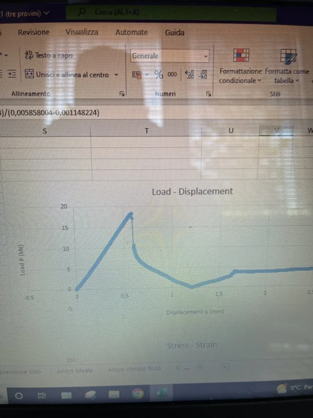
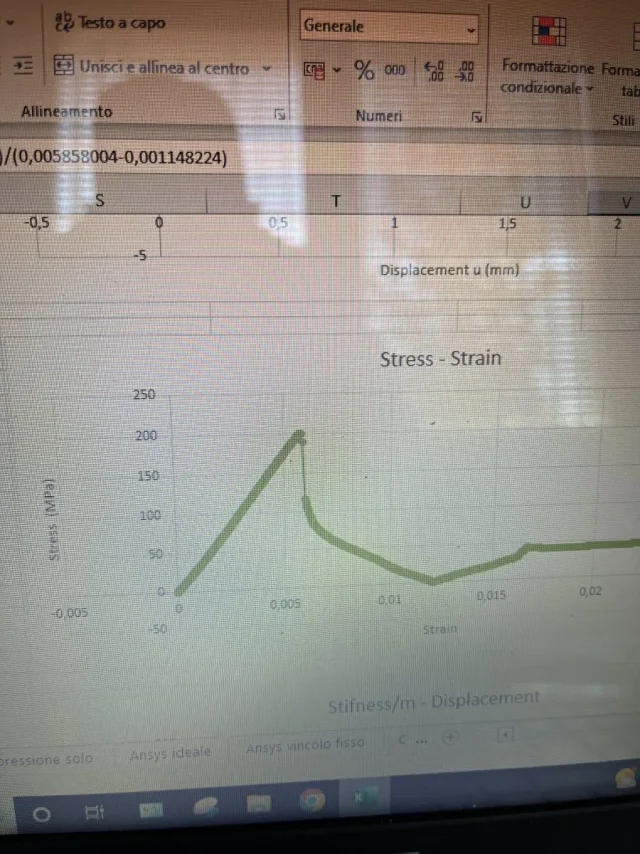
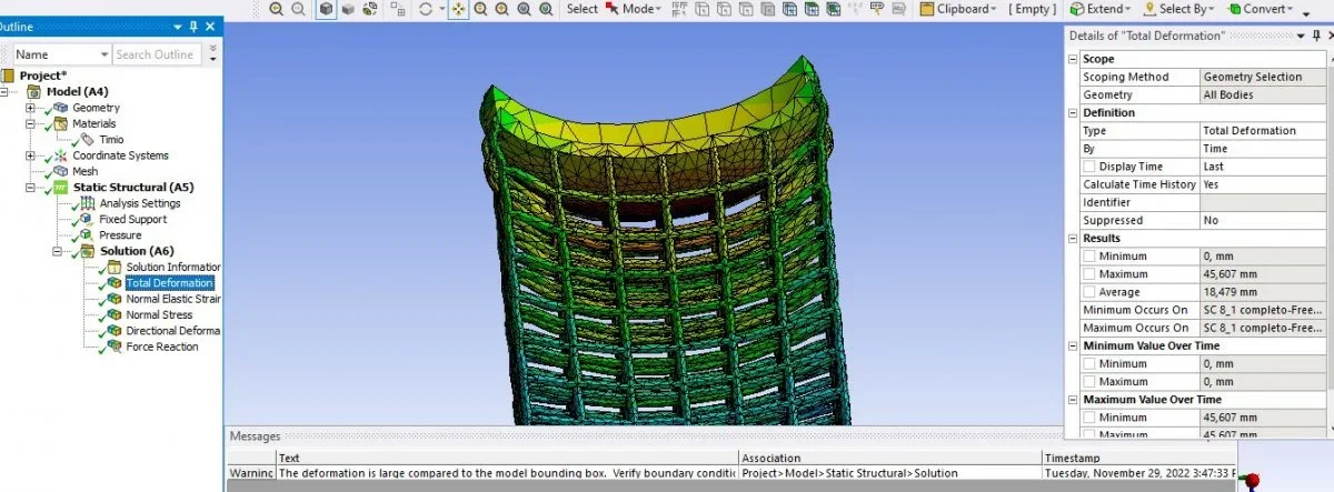
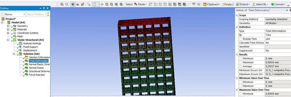
code aster is opensource. a little ostic, but a great sw.
 
then I try to answer everyone together with a single message, ansys does not give the possibility to import a 3d of only lines, even saving it in .step, does not recognize it as part or solid. So I can't do any tests. As for the plastic part, I divided the analysis into several steps and I think it succeeded, although with experimental data I can't find it. I would have another question to ask you, would you tell me why if I put a pressure on the upper face I get this deformed (even pressure on the upper face) while if I take a move this other one? are very different the two behaviors
 

Attachments

  • pressione.webp
    pressione.webp
    93.2 KB · Views: 9
  • spostamento.webp
    spostamento.webp
    69.6 KB · Views: 11
Yes, but holy patience, you think the way to ask a question.. ?

you don't see where you applied loads and constraints. .

in one image your structure has boarded, in the other it has remained straight.. Why? boh.

pressure of how much? is it equivalent to induced shift? evidently not if a structure deforms of 45 mm (you do not understand in what direction) is the other half a millimeter, this time evidently in vertical direction ..

It's impossible to give you an answer like that. .
 
If you apply a move, look at the deformed doesn't make sense... because the maximum deformation will have to coincide with the shift you imposed on a knot or a face ... otherwise you have something wrong

test or simulation or do it in force control (and see that deformation induces) or in shift control (and see what stress triggers you in the structure)

the two approaches are equivalent only in the linear field. Since we said at first that we are doing an analysis with plasticization, you have to choose one of two methods to be consistent with the approach used to the extent you want to compare.
 
then I try to answer everyone together with a single message, ansys does not give the possibility to import a 3d of only lines, even saving it in .step, does not recognize it as part or solid. So I can't do any tests. As for the plastic part, I divided the analysis into several steps and I think it succeeded, although with experimental data I can't find it. I would have another question to ask you, would you tell me why if I put a pressure on the upper face I get this deformed (even pressure on the upper face) while if I take a move this other one? are very different the two behaviors
for using beam elements on ansys mechanical I recommend this video. inter alia it explains well the interaction and construction of beam and shell elements that very often simplify geometry and speed the calculation (where their application is reasonable).
 

Forum statistics

Threads
44,997
Messages
339,767
Members
4
Latest member
ibt

Members online

No members online now.
Back
Top