• This forum is the machine-generated translation of www.cad3d.it/forum1 - the Italian design community. Several terms are not translated correctly.

set a tree with traction-flying-torsion,principle help

  • Thread starter Thread starter bulfy98
  • Start date Start date

bulfy98

Guest
Bye to all,
are at the very first experiences with ansys and the university asked me to compare analytical results and fem analysis for different trees with p=80kn traction, a bending and a torsion of 300nm each. all applied separately and in static with static structural.
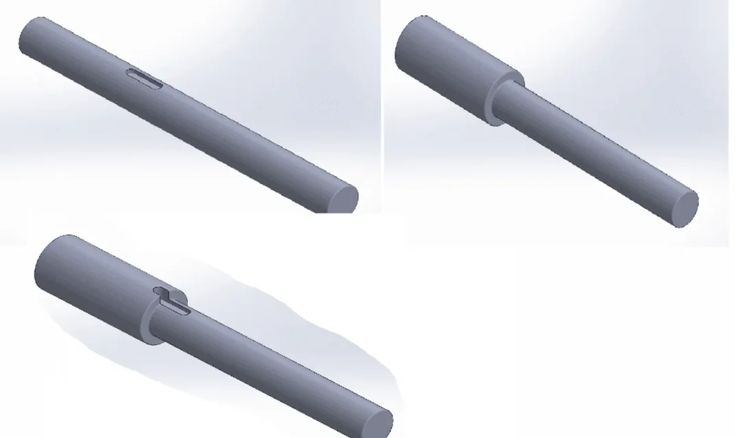
the trees are(I attach photos):
-d=45mm d=30mm shoulder with fitting r=1mm
-d=30mm with key seat
-d=45mm d=30mm with shoulder r=1 and seat for key that crosses the section
-d=192mm d=180mm shoulder with fitting r=4mm
My doubts, being novice, are the most trivial.
I have performed analytical calculations for all trees (except for the third of some nothing is present in literature) taking into account the kt carving factor and calculated tensions with von mises.

to compare the analytical results with the fem,how should I set the program? in particular:
-What stress calculation to adopt? equivanet von mises,normal,share? especially how to set them? I am always using equivalent von mises but sometimes the result does not converge well. What do you think?
-I would like to adopt a mesh of 1mm near the critical areas and wider elsewhere. How do you recommend doing this?

ps if you could motivate your choices you would make me a great pleasure, so understand why one so be the other not and learn more and more about this program.


thanks to all
 
there is no photo attached.

ansys classic or workbench?

You have different stresses that create sigma and tau efforts.. It seems clear to me that the overall state of effort should be analyzed with the criterion of von mises .. is what you should do also in pen calculation.
 
Bye. If you place the image we can help you. composite actions necessarily require analysis with von mises.

The third case doesn't have literature, you talk about a stick that passes the whole circular section. I imagine myself an asola that cuts the circular section like that to block the bitten cones.
I think in literature it can be considered a circular hole... because if it were a sunshade, you would have the shadow effect.
 
ansys workbench.
Sorry, I felt bad. I consider the stresses applied individually,in the sense before I analyze the tension for the only traction effort, then for the only moment in bending and in a third analysis I see the tension with torque moment.

I have doubts regarding the criterion to use because prof wrote this to me, but I do not know whether it is the best choice for a comparison with the analytical solution.

"- for traction I would not consider sigma eq. but the seal along the axis of the tree
- for the bending I would not consider sigma eq. but the seal along the axis of the tree
- for the twist the tau on the normal plane to the axis of the tree "Immagine.webp
 
Bye. If you place the image we can help you. composite actions necessarily require analysis with von mises.

The third case doesn't have literature, you talk about a stick that passes the whole circular section. I imagine myself an asola that cuts the circular section like that to block the bitten cones.
I think in literature it can be considered a circular hole... because if it were a sunshade, you would have the shadow effect.
You're right, he doesn't have literature. In fact, in that case it is not a real comparison, but only to assess the tensions. But I have the scruple to set up the program for previous cases to the best, so as to have a result as reliable as possible.

I have expressed myself badly, for each tree I consider the stresses applied individually. in the sense: first analysis only traction,second only bending and third only torsion.
 
ok then for each tree you have to activate only one stress at a time. when you go to see the results for traction stress you will have a sigma along the shaft axis, the tau will be null and the sigma of von mises will be equal to the traction sigma (unless numerical approximations).

and so on for other stresses. . .

I sincerely did not understand where the problem is in the analysis setting.

the question concerning the effects of carving instead is less trivial and should also be studied to vary the parameters of mesh (dimension and order of the elements)
 
I have expressed myself badly, for each tree I consider the stresses applied individually. in the sense: first analysis only traction,second only bending and third only torsion.
Okay, you corrected yourself when I answered you.

Well then the question is only about the effects of carving. post the results by hand and with the fem and see where the differences are, if there are.
 
Here are the pictures. In fact, the seat of the tongue and not a key is on the lower diameter shaft and continues to rub on the other diameter to have the maximum length of the same.
the third case should be a kind of sum or overlap of the effects of previous cases.
If so you would find a match between theory and fem. you have to find out correctly applying the study on two simple and known cases.
 
so much to give you an idea about the mesh size, it would be good where you study the carvings, have at least three elements of the smaller geometric dimension ... i.e. if I have a 1mm radius I have to have the mesh from 1/3=0,33mm in the portion around the carving.
a recent example you can see in my analysis on This is. Just look at the difference between constant and adaptable mesh 8mm with minimum automatic (about 1mm) up to 10 mm maximum.
Thank you very much for the tip, I will use this method and I will let you know
 
Okay, you corrected yourself when I answered you.

Well then the question is only about the effects of carving. post the results by hand and with the fem and see where the differences are, if there are.
I got back with 50mpa of difference! But now I will use the mesh you have recommended and I will show you both the analytical results and fem for the first tree.
Thank you
 
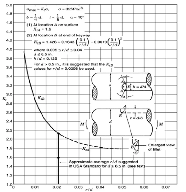
hi guys, I would like a feedback on this kt. implementing the formula to me came out 2 kt for zone b: 3,463 and 2.172. the first using the r/d ratio and the second using r/d=0.0208 as indicated by the formula for d>=6. What do you think is more correct to use?kt sede chiavetta.webp
 
Obviously you have two kt one on the bottom and one on the radius...just read well though.
careful that 6.5 are inches and therefore only if the diameters are greater than 165,1mm consider.
you can implement this for the seat that passes its diameters... .
 
Here I am, there I am! :
I sent the first results to the prof and she responded this way, could you give me a hand to interpret his demands?

-"make a small mesh (critery is r/1,33 or even smaller if it succeeds) on the shoulder we say for 5 mm on the right and for 5 mm on the left "
the mesh that I used riding the shoulder was the one that you recommended me with size r/3, which I find very valid, but I do not understand how to make this mesh to 5 cm and dx and shoulder sx

- "instead of "normal stress" fails to display sigmazz (if z is the shaft axis?) for traction and bending ". I do not understand how to view this sigma along the axis(which command is)

-" also try to make comparison not on the tensions but on the kt i.e. with the fem calculates the ratio between tension in the radius of connection and nominal voltage and compares it with the analytic kt "
Is there a way of doing this on ansys or do you think she intends to be done by hand?

ps my results were coarsely reliable, the only problems were found traction for the shaft with shouldering

Thank you very much for the help

.
 
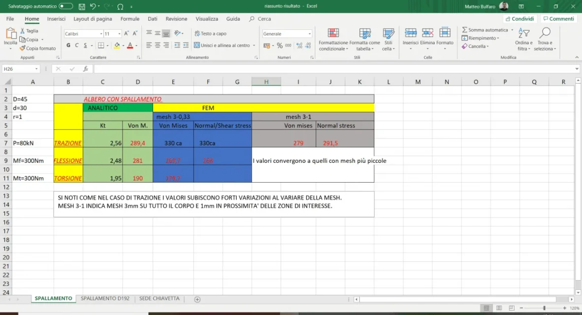
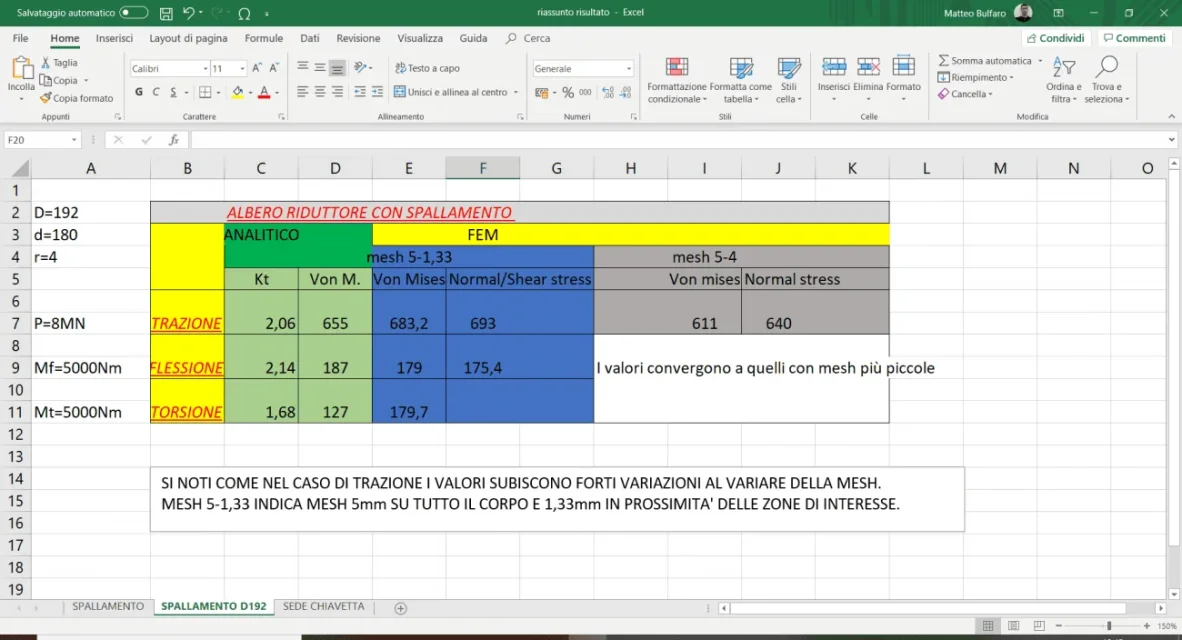
1586968883885.pngI bring back the results!! Sorry!! Here is the table of results for that tree, note that the values are very different to traction
 
Here I am, there I am! :
I sent the first results to the prof and she responded this way, could you give me a hand to interpret his demands?

-"make a small mesh (critery is r/1,33 or even smaller if it succeeds) on the shoulder we say for 5 mm on the right and for 5 mm on the left "
the mesh that I used riding the shoulder was the one that you recommended me with size r/3, which I find very valid, but I do not understand how to make this mesh to 5 cm and dx and shoulder sx

- "instead of "normal stress" fails to display sigmazz (if z is the shaft axis?) for traction and bending ". I do not understand how to view this sigma along the axis(which command is)

-" also try to make comparison not on the tensions but on the kt i.e. with the fem calculates the ratio between tension in the radius of connection and nominal voltage and compares it with the analytic kt "
Is there a way of doing this on ansys or do you think she intends to be done by hand?

ps my results were coarsely reliable, the only problems were found traction for the shaft with shouldering

Thank you very much for the help

.
I can't help you because I'm more than 15 years old than I do. However normally a fem allows to display as output different things, stress von mises, main tensions etc.
r/1,33 I have no idea....you can use it if you have to make a radius of 4-5mm.

the calculation of the kt made via fem it is necessary to apply the same loads with the same mesh possibly.... to try without carving and take the number. compare it to what comes out of the model that has the carving. report... that's kt.
 
Bye to all,
are at the very first experiences with ansys and the university asked me to compare analytical results and fem analysis for different trees with p=80kn traction, a bending and a torsion of 300nm each. all applied separately and in static with static structural.
the trees are(I attach photos):
-d=45mm d=30mm shoulder with fitting r=1mm
-d=30mm with key seat
-d=45mm d=30mm with shoulder r=1 and seat for key that crosses the section
-d=192mm d=180mm shoulder with fitting r=4mm
My doubts, being novice, are the most trivial.
I have performed analytical calculations for all trees (except for the third of some nothing is present in literature) taking into account the kt carving factor and calculated tensions with von mises.

to compare the analytical results with the fem,how should I set the program? in particular:
-What stress calculation to adopt? equivanet von mises,normal,share? especially how to set them? I am always using equivalent von mises but sometimes the result does not converge well. What do you think?
-I would like to adopt a mesh of 1mm near the critical areas and wider elsewhere. How do you recommend doing this?

ps if you could motivate your choices you would make me a great pleasure, so understand why one so be the other not and learn more and more about this program.


thanks to all
I was out of curiosity looking at one of your cases.

two diameter shaft, 40/35 with 1mm radius, 300nm torque.

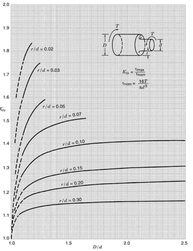
then I went to take the curves on a specialized manual and then made a couple of accounts with the parameters.

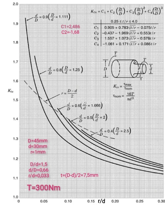
The curves I used are this:Screenshot_20200418_143957.jpg- I can't use it because with d/d=1.5 on the curve r/d=0,033 I don't have the curve... and so how do I invent it? I have to interpolate, invent, prolong etc.

and this:IMG_20200418_143742.jpg- I can't use it because t/r can't be more than 4
- when I fell my eye on this I stopped calculating the various coefficients c

but how did you calculate the theoretical value kt?
 

Forum statistics

Threads
44,997
Messages
339,767
Members
4
Latest member
ibt

Members online

No members online now.
Back
Top