• This forum is the machine-generated translation of www.cad3d.it/forum1 - the Italian design community. Several terms are not translated correctly.

size pump branched circuit

Matricola99

Guest
Good morning, everyone!

I'm sorry to disturb you, but I have a doubt that I can't clarify:
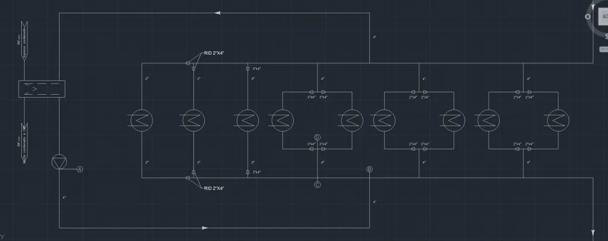
I would point out that hydraulics is not my basic discipline, I would like to understand how to dimensional the pump that serves to feed these utilities in parallel in a closed circuit and how to draw the characteristic curve of the system (linked file).
as you see it is a cooling circuit that serves different utilities.
the approach I used is to calculate the load losses in each branch and in each conduit with the respective scope and sum the load losses of the branches in parallel, so to understand the ab ho conduit I calculated the pdc with total flow, in the bc le pdc conduit with the flow that passes in that conduct... how do I design the curve of the plant? ? ?
Unfortunately I cannot find any practical example. .
Thank you very much
 

Attachments

  • Cattura.webp
    Cattura.webp
    12.4 KB · Views: 28
some info:
  • which fluid passes inside the hydraulic circuit?
  • Do you know how much the total flow is?
  • the lines to the right to what do they serve?
 
some info:
  • which fluid passes inside the hydraulic circuit?
  • Do you know how much the total flow is?
  • the lines to the right to what do they serve?
I answer you below;
- the fluid is cooling water tmin 24gradi tmax 30gradi
- the flow produced by the pump is 60m3/h
- the most right lines are connections to a larger circuit equipped with its own pump, my goal was to calculate the pressure at the exit point (where the arrow is) to win the pressure coming from the other circuit. . .
 
Then.
I would try to do so (for the first part).
not considering the two branches belonging to the larger circuit (the two lines to the right to mean us).Discussione dimensionamento Pompa idraulica.pngall utilities, including between the "b" node and the upper branch that connects with the line coming from the big "o" circuit in parallel, the assimilo/inglobo in a "total" user ra* and heat exchanger at the entrance of the pump rb. both will absorb a certain deltah prevalence.
therefore the hydraulic power (that exchanged between the pump impeller and the fluid) is given by:[math]pot.idraulica=gamma*qtot*deltahtot[/math]range=specific water weight that you can take practically constant to 9806/9810 n/m^3;
qtot=volta volumetrica of the fluid in question that will be 60 m^3/h(convertito in m ^ 3 / s will be 0,016667);
delta all=sum of the prevalences between point 1 and point 5.the total prevalence I could estimate it but lack the lengths of all stretches of the pipes (intravvedo of the diameters expressed in in inches and reductions).So do the lengths and material with which the lines are made?
However, the total prevalence is equal to:[math]h1-h5=(h2-h3)+(h4-h5)[/math] (as considered) solo the losses created by the two utilities, which in hydraulic call them perdite concentrate).
if you also consider the losses due to the passage of the fluid along the channels/condottes, then the total prevalence will be:[math]h1-h5=(h1-h2)+(h2-h3)+(h3-h4)+(h4-h5)[/math]
n.b.= le red prevalence are those due to fluid passage in the pipelines (distributed losses) while the black are those due to the resistance that the fluid encounters in crossing the utilities (focused losses).
After that, hypothesize a certain global pump performance (usually around 85-90%) and divide the hydraulic power with this parameter. so doing, you get the power absorbed by the pump you need to move everything.
 
Last edited:
Obviously, you must always see that the prevalence in the input to the pump "5" is always greater than the npsh (if this is not verified, the pump goes to the cavitation).
I'll try to answer you again tomorrow night.
 
Then.
I would try to do so (for the first part).
not considering the two branches belonging to the larger circuit (the two lines to the right to mean us).View attachment 70072all utilities, including between the "b" node and the upper branch that connects with the line coming from the big "o" circuit in parallel, the assimilo/inglobo in a "total" user ra* and heat exchanger at the entrance of the pump rb. both will absorb a certain deltah prevalence.
therefore the hydraulic power (that exchanged between the pump impeller and the fluid) is given by:[math]pot.idraulica=gamma*qtot*deltahtot[/math]range=specific water weight that you can take practically constant to 9806/9810 n/m^3;
qtot=volta volumetrica of the fluid in question that will be 60 m^3/h(convertito in m ^ 3 / s will be 0,016667);
delta all=sum of the prevalences between point 1 and point 5.the total prevalence I could estimate it but lack the lengths of all stretches of the pipes (intravvedo of the diameters expressed in in inches and reductions).So do the lengths and material with which the lines are made?
However, the total prevalence is equal to:[math]h1-h5=(h2-h3)+(h4-h5)[/math] (as considered) solo the losses created by the two utilities, which in hydraulic call them perdite concentrate).
if you also consider the losses due to the passage of the fluid along the channels/condottes, then the total prevalence will be:[math]h1-h5=(h1-h2)+(h2-h3)+(h3-h4)+(h4-h5)[/math]
n.b.= le red prevalence are those due to fluid passage in the pipelines (distributed losses) while the black are those due to the resistance that the fluid encounters in crossing the utilities (focused losses).
After that, hypothesize a certain global pump performance (usually around 85-90%) and divide the hydraulic power with this parameter. so doing, you get the power absorbed by the pump you need to move everything.
This is exactly what I needed!
Thank you very much, you are helping me so much!
Anyway, I know all about the pipes and calculated the load losses both distributed and concentrated in all branches. the thing I miss is to calculate the prevalence of the pump (which is the element to be sized and buy).
the further difficulty is that this circuit goes into a larger circuit with its pump and therefore I should put together the two things I do not understand how to do.
 
Ragionamento circuito idraulico-1.PNGI was thinking:
  • you could use the law of gauss in the circuit of your interest (the one between the black vertical lines:
[math](summ of the input flow in the circuit)-(summ of the output flow)=variation of the mass circulating in the system over time[/math]
  • Are you sure about the direction of flows? because, as you drew the circuit, the low line is where the prevalence/pressure fluid passes (not by chance, it is connected to the two pumps put in parallel to the left of your large circuit) while the top line is that of recirculation that returns to the valley (or rather, that returns from the pumps, which will recompress the flow of water and give it new pressure). you have no way to verify whether what you have designed is right or not, I refer to the direction of flows (circled in red).Ragionamento circuito idraulico-2.PNG
n.b. : green lines represent the path of the flow of water passing from the node v, present in the low line (high pressure) and going in the direction of the node, present on the high line (low pressure). then I thought I would put an "on/off" valve in order to adjust the flow rate or deviate the fluid path (beta valves) and a "non-return" valve for the alpha valve.
 
View attachment 70121I was thinking:
  • you could use the law of gauss in the circuit of your interest (the one between the black vertical lines:
[math](summ of the input flow in the circuit)-(summ of the output flow)=variation of the mass circulating in the system over time[/math]
  • Are you sure about the direction of flows? because, as you drew the circuit, the low line is where the prevalence/pressure fluid passes (not by chance, it is connected to the two pumps put in parallel to the left of your large circuit) while the top line is that of recirculation that returns to the valley (or rather, that returns from the pumps, which will recompress the flow of water and give it new pressure). you have no way to verify whether what you have designed is right or not, I refer to the direction of flows (circled in red).View attachment 70122
n.b. : green lines represent the path of the flow of water passing from the node v, present in the low line (high pressure) and going in the direction of the node, present on the high line (low pressure). then I thought I would put an "on/off" valve in order to adjust the flow rate or deviate the fluid path (beta valves) and a "non-return" valve for the alpha valve.
Good morning.

the direction of the flows are correct, or better, I have to dimension the single pump (in point a) so that they are, so that a small part of the flow elaborated by the pump goes into the bigger circuit and then back.
to do this I should balance the pressure coming from the small circuit to the one coming from the big one? but how to do it?
Thank you.
 
ciao @fresh.
I felt sorry for a while I was busy.
  • the direction of the flows and the values of the volumetric flow you know only. therefore for that part of the circuit (the one that is connected to the pump), it identifies all the courses and the respective directions inside it;
  • to estimate the pressure at the entrance of that branch (which we will call p2 ) you could use bernoulli between the beginning of the junction/biforcation of the node m (which will be the point 1) and the point 2. as in the image below;
IMG_8872.webp
  • to estimate pressure at the branch exit (which we will call p6 ) you can also use in this case bernoulli, as I described in the image below attached;
IMG_8873.webp
 
in one of my posts (I refer to post #6), I told you that the circuit that describes your branch is a "closed" circuit but, looking better and rereading your design better, is an "open" circuit (so I apologize).
the curve that describes the characteristic of the plant is a parable of the type:[math]y=ax^2+c[/math]then:[math]\delta h implant=\delta h static + \delta hdinamico[/math][math]\delta h plant=\frac{\delta p}{γ}+ kcircuit*qpompa^2[/math]Discussione pompa-3.JPGalong the branch where the pump will be installed, you will have to estimate/evaluate the load losses concentrate (such as the presence of elbow curves and the presence of the exchanger) and distributed (such as straight strokes of conduct,using moody abacus to estimate the friction coefficient of darcy). After that, replace the water flow rate c2 with q/a2 and collect all parameters that are not q. so you will get the k parameter that represents the concavity of the parable described above. the impact of the exchanger could take it equal to "2.5" (found on some files on the internet) while for the elbow curves of 90° you could take 1 or 1.5 (in the coming days I try to search).Discussione pompa-1.JPGDiscussione pompa-2.JPGn.b.:make an excel file where you enter all these data, type length of straight strokes, internal diameters, darcy coefficients, types of incidences,etc) and then, for each flow value, you will calculate the prevalence of the system. do this, you will be able to trace the curve of the parable on a xy chart where, on the axis of y you will have the prevails and on those of x volumetric flow rates.
 
other thing. the coefficient of darcy [math]\lambda[/math] depends on the type of regime in which your fluid is located (then you use the number of reynolds king) and the relative shelving of your conduct (adimensional number that relates the absolute roughness of the material and the inner diameter). with these two parameters, insert them into the moody diagram and get your [math]\lambda[/math].
After all these leaks, you should choose a pump supplier and get its catalog, where it shows you the performance of its pumps (as for the pdf catalog attached to this post--->pag.13). when you choose the pump, you will need to check that the pressure in the pump you choose is not too low (cavitation---> npsh)
I admit that my calligraphy is not the best, but if there is something incomprehensible, let me know.
 

Attachments

Forum statistics

Threads
44,997
Messages
339,767
Members
4
Latest member
ibt

Members online

No members online now.
Back
Top