• This forum is the machine-generated translation of www.cad3d.it/forum1 - the Italian design community. Several terms are not translated correctly.

support for correct sheet metal development

Hybrid

Guest
Good morning, everyone! I need a hand to properly develop the attached project. Is there a way to do it with inventor 2016? solid edge had the command to bend to diamond, in inventor I do not see it; but above all I need the correct material to then cut it to the laser and fold the 4 corners. being a liquid tank, the waste must be up to 0.4 mmView attachment test sviluppo lamiera Z508162.dwg
 
then no suggestion? I need to understand how to set the program so that it does everything from one sheet of sheet
 
for diamanting, there is a special command to create graphics in the flat model;
diamond is not a developable form.
 
I'm sorry I didn't understand one thing, you want to do that tray just by bending the four sides and getting that slope for deformation?
I'm not able to give you a hand and I'd be very interested in seeing how you would!
I would cut in correspondence of the trunchette/manicotto the 45mm that remain above I piego everything and balance.
 
for diamanting, there is a special command to create graphics in the flat model;
diamond is not a developable form.
Where do I find him? I tried to find him but without success... not "diamanto" often but is definitely useful!
 
open the flat model and look in its editing commands (in its icons. . )
after 4 hours of trial I managed... everything in manual obviously, moving faces and cutting. As soon as I can train the 3d and everything. machine cmq! As soon as the bender realizes the piece and it is correct there place a photo but it was a birth because cmq the fold needs overmetal and geometries its
 
that is not a diamantment, it is a distinct figure and different from the deformed plan you get with the diamantatura.
Anyway, I would have made it by modeling a solid and then getting the surfaces to thicken, you do first.
 
that is not a diamantment, it is a distinct figure and different from the deformed plan you get with the diamantatura.
Anyway, I would have made it by modeling a solid and then getting the surfaces to thicken, you do first.
to me it does not seem that turning it into sheet metal brings me back the correct development; doing so I have a perfect sheet that needs laser cut and then bent by the press fold leaving in the edges an air thread for the welding of the measurement that I want without considering that so I can set the k factor of the machines that I have in the company and I have a real development of the sheet. none of my customers can now provide me with a proper sheet metal development!
 
So, I only saw this discussion today, and what I'm saying, or is that what you ask with the drawing you posted at the beginning of the discussion, it's not a mismatch, so it's right to do it as you did, I just added that I would have made it starting solid because it first forms.
then I don't see why you can't get a proper development.
What version of inventor do you have? if you have 2016, I place you a file with the exact development
 
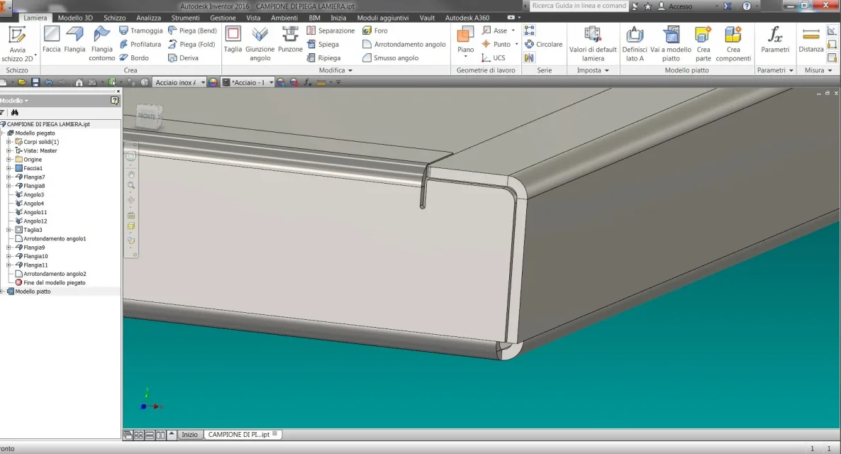
I appreciate the help of both but at carpentry level reality is different. First of all there is the discourse of the folds. in the first case there are no, in the second they are not good; need specific discharges otherwise the sheet does the bugna. then there is the short side fold speech and its coupling with the long side. the bending machine needs to fold before the short side which then has to protrude on the long side (and in the second case are equal) and all the relative discharges that go into conflict. Moreover less welding is less labor and more tight (it is a tray/water tank). to understand these are the angles as we do them (with 0.4mm air between the contact surfaces! )
Moreover for the laser to cut better (less gag, more speed etc...) all the discharges should be connected (no straight angles and the two discharge should not be square as above but in the development must be round with center in the crossroads of the fold axes)
Immagine.webp
 
Okay, so do I work with the sheet... calculates that I but I also believe others, I made you a file as an example, so without taking too much care of the detail of the discharges and the scans etc etc.
 
Okay, so do I work with the sheet... calculates that I but I also believe others, I made you a file as an example, so without taking too much care of the detail of the discharges and the scans etc etc.
and but it's just the drains and grooves that cause me errors in the program that I asked for advice.
 

Forum statistics

Threads
44,997
Messages
339,767
Members
4
Latest member
ibt

Members online

No members online now.
Back
Top