• This forum is the machine-generated translation of www.cad3d.it/forum1 - the Italian design community. Several terms are not translated correctly.

symbols used in construction plans

  • Thread starter Thread starter Messerschmitt
  • Start date Start date

Messerschmitt

Guest
Good evening, everyone.
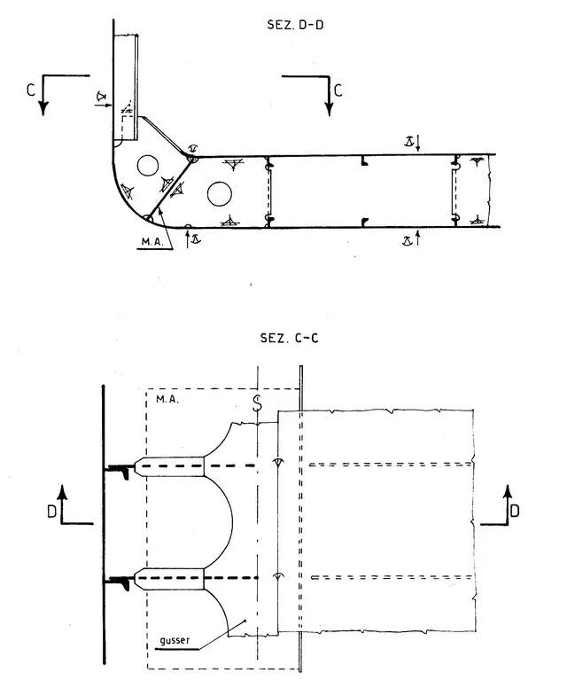
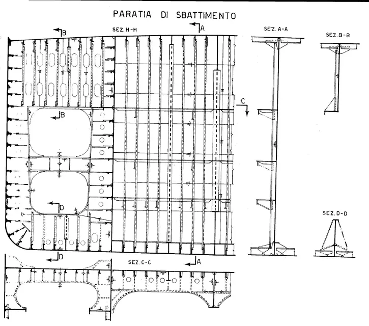
I am studying the designs of the construction plans of a small ship. the hull is geometrically very simple, as it consists only of plain surfaces or simple curvature.
I would like to know if I am correctly interpreting some symbols that I found:

- where the profile used as a current changes $.

- on the horse of the lines indicating a variation of thickness of the strip there is a |=|.

- the lines that indicate a edge between two sheets (for example, at the aft there is the bottom band that passes from plate to incline) are indicated with a triangle type:_vThis symbol is also used when switching from a thick sheet to a thin sheet, and a tapering of the big sheet is required to bring it to the thickness of the thin one.

Sorry for the schematic representation of symbols, I hope you understand.. .

Anyway, do you have these symbols?
 
if on the drawing there are those symbols, you are not looking at the construction plan but a plan of the ferries.
the building plan in fact, does not bear constructive symbolism but is the representation of the geometric shapes of the hull. This is the triple orthogonal projection of the surface of the hull assuming which references a longitudinal plane parallel to the symmetry, a horizontal plane parallel to the full load floating plane and a normal transversal plane to the first two.

the dollar symbol, if placed on a cross section, represents a spike. You can see it in the carrier section that I attached to you.
if it is on a horizontal plane, as in the second attachment, indicates a line along which the union between two hidden elements takes place.
Maybe the image is clearer.

the two parallel lines, for example, are placed on the floors of the bridges or, as in the third annex, on a bulkhead and indicate the welding to straight edges.

v usually indicates a soldering precisely to v.
it would still be easier to attach a part of the drawing, in particular I did not understand what it means "the lines that indicate a edge between two sheets (for example, at the stern there is the bottom bandage that passes from plate to incline) are indicated with a triangle"
 

Attachments

  • Scan1.webp
    Scan1.webp
    157.4 KB · Views: 44
  • Scan2.webp
    Scan2.webp
    84.9 KB · Views: 36
  • Scan3.webp
    Scan3.webp
    432.6 KB · Views: 34
I agree that the design in question is a plan of the needles.

the $, at least on the drawings with which I work, represents the locking joint. that is normally modern ships are prefabricated in assembly sections in turn constituted by blocks. the boundaries of these units are precisely indicated on the drawings with $.
You're right, in some tables I noticed that the joints of the blocks report that symbol.
 
those you have indicated are only three of the many symbols represented in the plan of the ferries. I have searched on many sites but I have not been able to find a table where everyone is reported. exists? Thank you.
 

Forum statistics

Threads
44,997
Messages
339,767
Members
4
Latest member
ibt

Members online

No members online now.
Back
Top