samuele.vecchi
Guest
Hello, everyone. I would need an opinion (with any shortcomings/corrections) on the table of a component of an epicloidal gearbox (especially with regard to the choice of geometric tolerances).
Last edited:
Good morning to you.Hello, everyone. I would need an opinion (with any shortcomings/corrections) on the table of a component of an epicloidal gearbox (especially with regard to the choice of geometric tolerances).

 now it indicates ra 0.8 below the root of the "carriola".
 Moreover they are more than 20 years that you no longer write "a-a-section" but you only write "a-a".
Thank you for the answer. I'm fixing.Slowly we'll give you a look at things.
the legislation for roughness is evolvendo with symbols and roughness. personally I have not yet found a cad that supports the iso 21920 but the iso 1302:2002 is supported.
Solidworks settings.. .View attachment 70775
View attachment 70774now it indicates ra 0.8 below the root of the "carriola".
the use of the arrow attached to the symbol is a bit of a force and therefore to avoid.
but always, it has never changed, the tip of roughness is turned... and always insists on the surface worked, never on the opposite one.View attachment 70773Moreover they are more than 20 years that you no longer write "a-a-section" but you only write "a-a".
the contours are 0,5mm thick and the fine lines 0.25. there is the norm that defines this....iso128-20.
in the axieme, if the section is made with arrows to the left.... the sectioned view goes to the left not to the right.
it is not that everything that allows a software is in accordance.
the diameter of the piercers 72 should be tolerated otherwise the location is not enough.
Thank you for the answer, the document will definitely help. As for the interest of the holes, sincerely, I have no clear how to tolerate it. Do I refer to eligible deviations?for geometric tolerances you can take inspiration from the design on page 41 of this documentHowever, considering that the whole of the holes should also be tolerated.
Yes, I as earth values 72 +/- 0.01.As for the interest of the holes, sincerely, I have no clear how to tolerate it. Do I refer to eligible deviations?
personally, that I am more focused on a practical approach, it is worth more a tolerance of ±0,01 and I would not place the location....but look good, it is right that both are there.Thank you for the answer, the document will definitely help. As for the interest of the holes, sincerely, I have no clear how to tolerate it. Do I refer to eligible deviations?
(1)I thank you again for the answer and for the kindness. I just wanted to ask for 3 more things:
1) is it correct to repeat the localization and parallel tolerances for the 2 holes (as done in the drawing) being different holes?
2) in the conical hole I used both a dimensional tolerance h7 and a geometric tolerance of circularity but according to you are both necessary or go only to weigh the design?
3) would it be appropriate to insert a roughness of 1.6 on the surface where the rosette rests and perhaps a dimensional tolerance in the hole diameter 6.5 mm where the screw passes or can I leave so?
Thank you for the answer. So you think the two datums and I should reposition them? and in any case the two parallel tolerances can be omitted? Besides, do you need to add/modify some other geometric/dimensional tolerance?a very serious thing is to indicate the drfs on axes, as well as tolerances. The axes are never touched.
Parallelism (on axes by the way) does not serve once you have defined the tolerance of location.
where I could reposition themThank you for the answer. So you think the two datums and I should reposition them? and in any case the two parallel tolerances can be omitted? Besides, do you need to add/modify some other geometric/dimensional tolerance?
I looked at the drawing of the document shared but according to what said by biz I seem to understand that there are several errors also in it. Right? I do not understand whether reporting tolerances and datum to axes is actually a mistake by norm or rather something to avoid preferably. I'm kind of confused.for geometric tolerances you can take inspiration from the design on page 41 of this documentHowever, considering that the whole of the holes should also be tolerated.
Thank you again for the answer. I attach the modified design. I added a datum d as reference for the tolerance of perpendicularity as it seemed more appropriate to take as reference the axis of the hole itself (is it correct?). I also eliminated the dimensional tolerance on the diameter of 72.is correct the statement of News; guard document to pag. 2-3 and, to expand your knowledge, also quest'altro on the recent gd&t standard.
In your case, using the datum b on the outer diameter, implicitly assumes also its theoretical axis for which for the three conical holes I would keep the localization tolerance referred to b and, at this point, I would remove the tolerance on the diameter (axis) 72.
the same you will have to do with the diameter (center) 12 h7. These two geometric localization tolerances would match the odds of the respective holes in the view in section, possibly indicating the number of holes.
observing the design of the component and the axieme I would like to make some comments:
- the depth of 0.5 mm of the 12 h7 centering is not functional, considering the bevel on your component and that on the counterpiece (necessary) you will find an unexisting centering.
- also the thickness of 1.5 mm of material where the screw m6 works seems to me to be small; You can increase them by reducing the height of the screw head (using low-headed tcei).
- from the overall it seems that when you fix your component (14) you have two references of jokes (12 h7 and 12.6 h7 conical) of which one is too much. if it acts first the conical is fine, but if it goes first in joke on the 12 h7 the conical tree is no longer stuck and being able to block them both at the same time is very difficult.
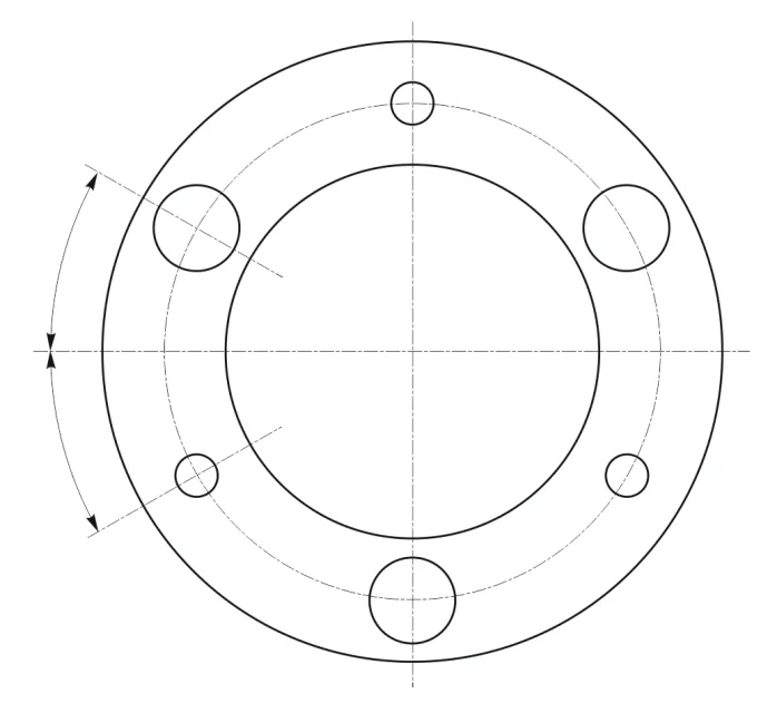
- I would also insert the angle of the holes that are not on the axles.
- I do not know how the male part of the centering on the counterpiece is obtained, but instead of three centerings of 12 h7 I would do only one to 82 h7 working also the corresponding counterpiece; this observation take it with reserve because I do not know how component 5 is made.
Yes, in fact the holes are few and easily recognizable.- I am not convinced to add the number of holes because otherwise I should not do the same for the other odds like that of 6.5?
see image attached. In reality it is understood that there are 4 holes at 30° but I think an operator is more facilitated if he sees it written.- I did not understand the fourth point on the angle of the holes that are not on the axes.