• This forum is the machine-generated translation of www.cad3d.it/forum1 - the Italian design community. Several terms are not translated correctly.

test fatigue welding joint roller

Ing.Vedder

Guest
Good evening,
I have a two-sided roller created with a thick mechanical tube which at the ends welded two studs made with a full round bar on which the bearing supports skf are mounted.
I need to evaluate the fatigue resistance of the circumferential welding that joins the cog to the thick strong tube as from detail below.
I tried to look at both part 9 ec3 and the old uni7670 on the lifting devices (two norms that I always use as a reference for fatigue calculations) but I did not find a case similar to mine, the only thing is the particular 12 of the 8.5 outlook of the ec3 but does not convince me completely.
Would someone know how to indicate a manual verification path (at this stage no fem) for an angle welding of that type?

p.
the cod is welded to the pipe but being then a full round will also be planted in the pipe in interference, therefore it is lawful to think that the soldering will work "less" of what can be thought. However I would like to find a method of calculation as if I had to rely 100% on the soldering in question


Thank you all! !
 
if the tube is inserted with interference, as we normally do, it is he who has to keep torsion. compression/cut on the graft. welding is of beauty and is made to improve the joint capacity. if it cliques means that interference is nonexistent.
As described in the Eurocidice 3 uni en iso 1993-1-8, the welding cord must be checked statically, imposing in your case that it is only he to carry the load. to do this are described two methods: simplified method and method of overturned tensions (absolute to the old cnr uni 10011 now withdrawn from twenty years).
for fatigue analysis there is the sigma/number cycle method with the miner method as uto in Annex 5.
Moreover to complete the thing, for the various formulas you must also use uni en iso 1993-1-9.

to do fem analysis, it is not enough to do it statically but it is necessary to use a fine mesh and to use the methyl hot spot stress on three points and it is a procedure however not very easy.

In fact even the calculation normally requires a little time, effort, reckoning and putting it definitely in excel and speeding things up.
 
the tang is planted in interference in the tube, but what worries me is not the torsion of the motor (it is a motorized roller), but the flexional and cutting loads deriving from the load that passes on it (variate tons, with frequency of thousands of cycles die).
Despite this, however, I would like to try to dimensional as if everything (flavor, cut and twist) went through the corner cord.

the static verification of the cord does not bother me, I take throat height, rebound and I find the various sigma that then combine, okay.
I'm worried because I don't find a methodology to use, on the 1993-1-9 uni en iso (norms designed more for carpentry than for a mechanical roller) I don't think that any detail of fatigue between those presented is my case.
Finally, you mention Annex 5 but I am sorry I did not understand what norm.

hot spots are a way but as you said it is long and complex therefore I would keep it as the last beach and definitely not at this stage of the project.


Thanks a thousand mechanicsmg for the help!
 
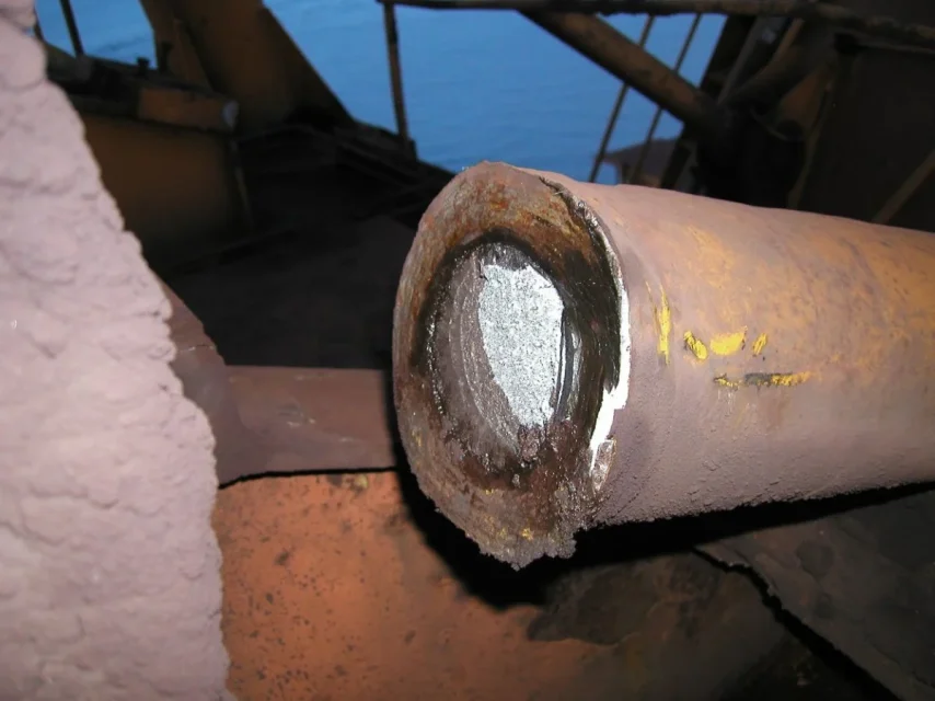
In the past, I had an accident in a similar situation: being beauty welding, it had as a practical effect that to hide the situation below, until the clique in the base metal did not propagate beyond the limit and welding, of course, has torn.P1010025.webp
 
try to take inspiration from qui
thanks for the link, it seems interesting.

reading what I understand is precisely the fact that for calculations "hand" you have to know from literature the s-n curve associated with your fatigue detail to find the tensions in play and to make reasoning on fatigue life. .
and that's where the problem comes to me: I don't have a s-n curve to do it again, and here I cry!
 
In the past, I had an accident in a similar situation: being beauty welding, it had as a practical effect that to hide the situation below, until the clique in the base metal did not propagate beyond the limit and welding, of course, has torn.
I would use here the old uni7670 for the verification of the base metal that I imagine will be planted inside the tube up to a shoulder with consequent connection raggetto.
 
Unfortunately it was that too ino connection raggett, so much so that between zta and concentrations to the edge, started the clique with the result of the photo (it was a pull of movement a pantograph crane). the element was also checked periodically, but under welding inspection had no effectiveness
 

Forum statistics

Threads
44,997
Messages
339,767
Members
4
Latest member
ibt

Members online

No members online now.
Back
Top