• This forum is the machine-generated translation of www.cad3d.it/forum1 - the Italian design community. Several terms are not translated correctly.

where's the mistake?

  • Thread starter Thread starter ansyolitico
  • Start date Start date

ansyolitico

Guest
Hello everyone
I think I'm losing in a glass of water.
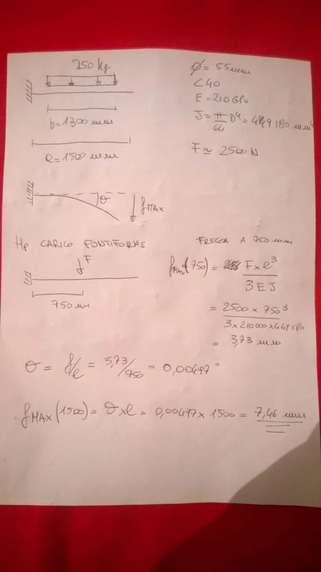
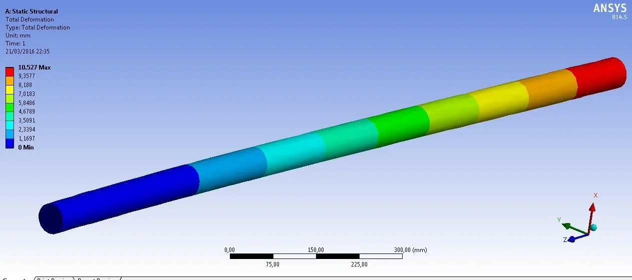
I have a simple round beam diameter 55 with a distributed load as from drawing....using the classic forms of structural mechanics I have a max arrow of 7.45 mm while with ansys I get a max arrow of about 10... in the analytical calculation I did not take into account the deformation of cut, only of the moment but there is almost a error of 40%...it seems a little too much for a neglect of the cut, besides everything I hypothesized dot load (to be on the side of the reason), so it should be increased, instead of it is minor, someone would know where I would be wrong?

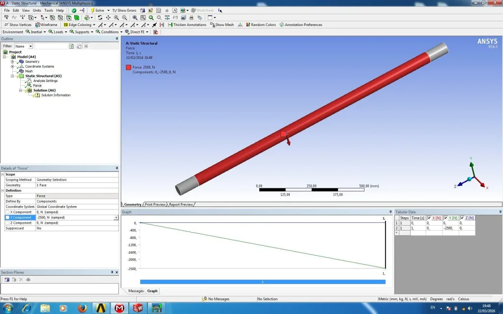
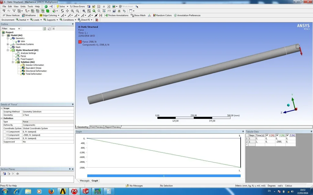
in ansys I put as fixed bond to the extreme of the bar and the load with vector component -2500n(y) on the face of the bar (I extruded previously by increasing a 1 mm diameter to define well the load surface)
WP_20160321_003.webpImage3.webp
 
distributed load, point load.... sorry but what do you use?
Are you using analytical theory (trave of de s. venant) and comparison with a fem?
Of course it changes something. How is your mesh?
You should compare with a calculation using auctions! not solid.
I don't understand how you put the loads in ansys and what you want to do... forgive me but either you have the automatic concealer or some word you missed!
 
They always told me to confront the fem with s. venant when possible. I think this is a possible case, right? simple round beam with a distributed load and the beam is not toast, it is not a linear analysis

on the analytical part I hypothesized to have a concentrated load to put me in a worse condition (the dot deforms more than a ditribute) just to simplify the accounts and do more quickly
the strange thing that with the accounts I should get a deformed greater than the fem in which I put a load distributed on the face (real case first pattern on the sheet) but it's not so...

The only thing that the fem considers extra is cutting deformation... but a 40% error seems to me, as I have already said, exaggerated only for this ommission... if I did virtual work I don't think it would be the same result of the fem.

Have they always told me shit? (maybe I was sleeping in class) or am I wrong?

in ansys I put distributed load of 2500 n and applied it on the face of the previously increased bar of 1 mm on the diamentro with the purpose only to be able to select it to apply the distributed load.

I forgot the mesh is the default one, I didn't even increase with the revelance.

(For errors I know I'm donkey, not concealer)
 
They always told me to confront the fem with s. venant when possible. I think this is a possible case, right? simple round beam with a distributed load and the beam is not toast, it is not a linear analysis
Did you make a mesh with square or linear elements? If you have used linear tetra elements you are in the worst situation, i.e. the system overestimates stiffness and therefore see a deformed lower than de san venant. If you use square hexedral elements, you will certainly approach the theory of beam. square tetra elements are a good compromise between not going crazy to make mesh and getting decent results.
 
Did you make a mesh with square or linear elements? If you have used linear tetra elements you are in the worst situation, i.e. the system overestimates stiffness and therefore see a deformed lower than de san venant. If you use square hexedral elements, you will certainly approach the theory of beam. square tetra elements are a good compromise between not going crazy to make mesh and getting decent results.
apart from the fact that in the workbench you can not choose the types of elements... only solid 3d... but if you should be as you say I should get a less deformed than the accounts. .. sincato that is the exact opposite
 
apart from the fact that in the workbench you can not choose the types of elements... only solid 3d... but if you should be as you say I should get a less deformed than the accounts. .. sincato that is the exact opposite
All right, have fun finding the solution then.
 
excuse but do you not want to use a beam3 element (2d) and make comparison? ? ?
If you use a 3d model you should model the distributed load in a circumferential way and it is not simple.
 
I don't think I can find the solution. I'm too a donkey. but hell I posted a photo of the results and one of the accounts I did (I hope right), at least look at them before writing... then for the love of the sky... I was not born learned, I can very well wrong. . I wouldn't be here posting if I didn't.
 
apart from the fact that in the workbench you can not choose the types of elements... only solid 3d... but if you should be as you say I should get a less deformed than the accounts. .. sincato that is the exact opposite
It seems to me that the calculation of the rotation of the section at the point of application of the load (word of the case with concentrated load). you calculated it simply as a relationship between the arrow and the half-length, which would be like to consider the undeformable beam over the whole length and consider all the deformation applied in the enclosure.
- - - updated - - -
I don't think I can find the solution. I'm too a donkey. but hell I posted a photo of the results and one of the accounts I did (I hope right), at least look at them before writing... then for the love of the sky... I was not born learned, I can very well wrong. . I wouldn't be here posting if I didn't.
It was just a way to make you notice that you put yourself a little rude (out of place) to a person who committed part of his time to respond.
 
I tried other cases
1_ round bar of 55 with distributed load and load at the end
2_barra square 90 with distributed load and load to the extreme

I compared with s. venant and fem (I know you could not do but they are simple bars, the only thing that can rub me is the thickness of the beams).
as a result I have obtained that the fem is less rigid than s. venant (and should be the opposite) but to logical rigor the contracted load flet more than the distributed one.

Now... what I don't understand... is like a simple trave s. venant doesn't get us... in one they explained that s. venant doesn't apply to the thick profiles, those for which hydraulic similarity cannot be hypothesized.
maybe it's me that I've wronged the accounts or I set wrong ansys(very likely)
Here are the reports
Image2.webp
Image4.webp
Image1.webpImage3.webpImage5.webpImage6.webp
 

Attachments

  • Image7.webp
    Image7.webp
    87.3 KB · Views: 0
  • Image8.webp
    Image8.webp
    92.4 KB · Views: 1
  • Image9.webp
    Image9.webp
    106.5 KB · Views: 0
  • Image10.webp
    Image10.webp
    92 KB · Views: 0
But who says ansys doesn't let you work on mesh?
question: Are you a self-taught or did you do some classes? If you answer with self-taught then better study before you start making calculations. ansys is not a toy, it is great tool to solve problems well placed!
Hi.
 
But who says ansys doesn't let you work on mesh?
question: Are you a self-taught or did you do some classes? If you answer with self-taught then better study before you start making calculations. ansys is not a toy, it is great tool to solve problems well placed!
Hi.
I'm sorry... I didn't do a course but I was for thesis in a design studio where they used ansys... and I saw that unfortunately ansys uses only brick elements I think... true that the mesh can be set but it doesn't allow you to choose the type of elements. . .

if it wasn't. ..to tell me where I could bang my head to learn
 
I don't have ansys now, but if you select the mesh menu, you'll find that you can help us.
You can force the kind of mesh but it's not said that you can do what you want.
watch the online help of the program
 

Forum statistics

Threads
44,997
Messages
339,767
Members
4
Latest member
ibt

Members online

No members online now.
Back
Top