• This forum is the machine-generated translation of www.cad3d.it/forum1 - the Italian design community. Several terms are not translated correctly.

design for wheels

  • Thread starter Thread starter Jockettino
  • Start date Start date

Jockettino

Guest
Good morning to all,
I am designing a rotary drum for the drying of the malt and I need your help to understand if I am correctly dimensionaling some elements. the drum has a diameter of 2800 mm and rests on two pairs of wheels. the total weight of the full load drum is about 16000 kg so each pair of wheels will support a weight of 80000 n.
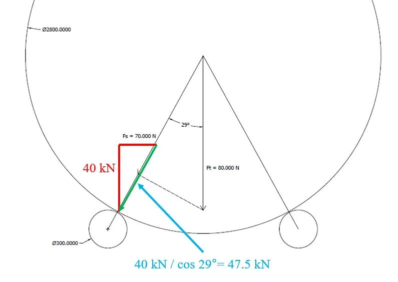
as you can see from the attached sketch the wheels of the torque are at step 1500 mm between them and decomposing the forces I find that each wheel has a load of about 70000 n.
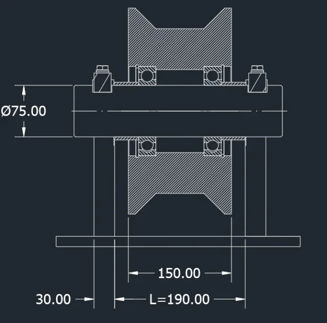
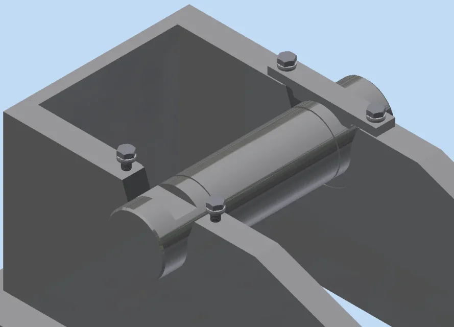
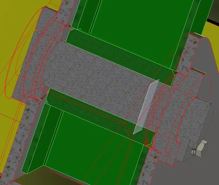
I attach my idea of wheel and pin, as you can see I have a pin to which I prevent the rotation on which I mount a wheel with a bronze stopped by a seger. The sketch has the final quotas derived from my accounts.
in this situation the pin is subject only to moment fs generated by force fs and with arm l/2. the pin I thought in c40 with a rm of 600 n/mm2 and a safety factor n=5. σamm = 120 n/mm2
with the bending pin sizing formulas results:
d=(32*mf)/(π*σamm)
d=(fs*l/2)/(π*σamm)
d=82.64 mm rolled to 85 mm

Whereas a l/d ratio of 1.5 is a 130 mm long bushing.
looking on the internet I found a commercial bronze bushing with dimensions ø85-ø100 l=130 mm.

for the base of support of the wheels I thought of a welded box of iron plates sp 30 mm with machine tooling.

I'm pretty sure of the accounts I've done but I ask you to confirm that sometimes I'm going to fossilize things that I think I'm right and then I realize I've made a mistake completely.

Thank you.
Mar
 

Attachments

Bye. If I count myself the disposition of the central force on the two directions is wrong. it should not be perpendicular but you have to pull the parallels to the decomposition directions. you have to get a roar with the diagonal plus the vector sum of the two side.
See you qui.
banally if you have 80kn in the center you can not have two supports that make 70kn....but you will get two reactions from 45,7kn.

hyper regarding the formulas to use I recommend you look on the niemann or on the forum because we have already discussed the application of the pins that to size you do as you want but the verification must have all the components.
if the side walls are rigid enough you will also have the cut.
 
the breakdown of forces should be like this:
(which should be as mentioned by mechanicalmg)1658144695605.webpI hope I didn't say shit. .
otherwise I gate the post
 
Bye. If I count myself the disposition of the central force on the two directions is wrong. it should not be perpendicular but you have to pull the parallels to the decomposition directions. you have to get a roar with the diagonal plus the vector sum of the two side.
See you qui.
banally if you have 80kn in the center you can not have two supports that make 70kn....but you will get two reactions from 45,7kn.

hyper regarding the formulas to use I recommend you look on the niemann or on the forum because we have already discussed the application of the pins that to size you do as you want but the verification must have all the components.
if the side walls are rigid enough you will also have the cut.
Thank you very much.
I didn't remember any of this kind of breakdown.
Now I look again for posts on the sizing of pins similar to my application hoping to be luckier.
 
Sorry, but I need another advice. the drum turns at 1.5 rpm and consequently the wheels will turn at 14 rpm. with such low speed is it absurd to put bearings? is it more correct to think of using sintered bronze bushings?
Thank you!
 
Sorry, but I need another advice. the drum turns at 1.5 rpm and consequently the wheels will turn at 14 rpm. with such low speed is it absurd to put bearings? is it more correct to think of using sintered bronze bushings?
I would still use shielded roller bearings, perhaps pre-lubrified, surely oversized, "mounted and forgotten" style.
 
I would still use shielded roller bearings, perhaps pre-lubrified, surely oversized, "mounted and forgotten" style.
I calculated my c0 load coefficient in this way:
== sync, corrected by elderman ==
p0 is my load of 47,500 n
for s0 that is the safety coefficient relative to the static load I opted for a 1.5
c0 = 47500*1.5 = 71.250 n
As you can see from my attached design my wheel is so large that I would opt to put 2 bearings on the sides so that I can divide the load on both bearings (35.6 kn).
thanks to the correction that you have done to me in the breakdown of the forces I calculated a pin with ø75 and on the site skf the bearing with adequate static load coefficient turns out to me 6215 (c0 = 49 kn).
the roller bearing of the same size (n 215 ecp) has a c0 of 156 kn that seems too oversized since I think I put two!
What do you think?1658157294163.webp
 
ft is your result, so the vector sum fs+fs, according to the rule of the parallelgram is given by:
ft=radq(fs^2+fs^2+2*fs*fs*cos(alpha))
alpha is the angle between the two carriers.

in practice is the formula of carnot changed of sign (if you read me a mathematician kills me).
I didn't count, but it looks like 70kn's okay.
to measure and verify the pin you can use niemann and/or eurocode 3 according to the coupling you have.
 
I calculated my c0 load coefficient in this way:
== sync, corrected by elderman ==
p0 is my load of 47,500 n
for s0 that is the safety coefficient relative to the static load I opted for a 1.5
c0 = 47500*1.5 = 71.250 n
As you can see from my attached design my wheel is so large that I would opt to put 2 bearings on the sides so that I can divide the load on both bearings (35.6 kn).
thanks to the correction that you have done to me in the breakdown of the forces I calculated a pin with ø75 and on the site skf the bearing with adequate static load coefficient turns out to me 6215 (c0 = 49 kn).
the roller bearing of the same size (n 215 ecp) has a c0 of 156 kn that seems too oversized since I think I put two!
What do you think?View attachment 66102
I see now how the assembly is. Well to dimensionalize in this case you use the base of science of construction. the collapsed pin for bending. the cut not to consider it exactly.
 
ft is your result, so the vector sum fs+fs, according to the rule of the parallelgram is given by:
ft=radq(fs^2+fs^2+2*fs*fs*cos(alpha))
alpha is the angle between the two carriers.

in practice is the formula of carnot changed of sign (if you read me a mathematician kills me).
I didn't count, but it looks like 70kn's okay.
to measure and verify the pin you can use niemann and/or eurocode 3 according to the coupling you have.
I wanted to write isn't good. the system would not be in balance.
 
with such a low regimen you can mount whatever you want. clearly that a bronzine makes more friction and has more maintenance. a roller or ball bearing, shielded and lubricated forget it as maintenance.
 
being this machine a rotating dryer subjected to heat/cooling cycles there will also be pushes in the sense of the main rotation axis. It is therefore necessary to take account of the size of the bearings. at least I would place a spacer on the pin between the bearings, otherwise in case of axial spins only one works. I see more than the wheel has a throat, I suppose to hold the drum. I remember now xx years ago a rotary dryer for chemicals, despite turning slowly, long to go the wheels and the ring were recalcling to each other producing important vibrations with death of bearings, so between in 6125 and a 6315 are few euros and the c0 increases of a 55%, melius abundare. . .
I would also tighten the shoulders, it does not need a space of 20 mm, it is enough 5, it decreases the bending on the pin.
 
I give you my impression:
- better shielded roller bearings.
- pin ø75 do ø80 c45 commercial chrome rectified.
- carpentry ears in a single piece or near the wheel, 20 mm are too many maximum 5 or better insert welded bushings so also increase the support of the pin.
-fermo tree with an axial stopper and anti-rotation also called din 15058 axis support.
everything is mounted by threading and pulling the pin so a head hole on both sides of the same for extractor would be comfortable.
I am quite certain that I would get a better system at a lower price.
in case you want to make the supports pin in two halves to facilitate the assembly and disassembly of the only wheel group, take the system above, including axial stop anti-rotation pin , and cuts in two not horizontal that not displaced it more but tilted of 29 degrees (radial in the tangence point of the drum ) ,coperchietti out to be able to dismantle it.
Then do all the calculations you want.
Ps:
Why 29 degrees? You can't do 30, so you can't make fun of the workshop.
pps :
at what temperature do you work presence of aggressive agents in the environment and in vapours/fumes?
ppps:
I see that the wheels have a plentiful containment in the sense of the drum axis (tilted plates), do you also have spins (forces) in that direction? If not reduce both the diameter and the thickness of the wheel and the iron (c45 + tempra induction ? nitro gaseous carburization ?) and the processing costs. Among other things, I think that you are forced to make a ring around the drum of at least 60 mm thick, perhaps even more if you consider the welds (proportion to the eye;) ).
 
being this machine a rotating dryer subjected to heat/cooling cycles there will also be pushes in the sense of the main rotation axis. It is therefore necessary to take account of the size of the bearings. at least I would place a spacer on the pin between the bearings, otherwise in case of axial spins only one works. I see more than the wheel has a throat, I suppose to hold the drum. I remember now xx years ago a rotary dryer for chemicals, despite turning slowly, long to go the wheels and the ring were recalcling to each other producing important vibrations with death of bearings, so between in 6125 and a 6315 are few euros and the c0 increases of a 55%, melius abundare. . .
I would also tighten the shoulders, it does not need a space of 20 mm, it is enough 5, it decreases the bending on the pin.
you understood the project perfectly as a whole.
the drum will be rotated through a chain wrapping on the drum strap and I calculated that I will have a dilation of about 11 mm.
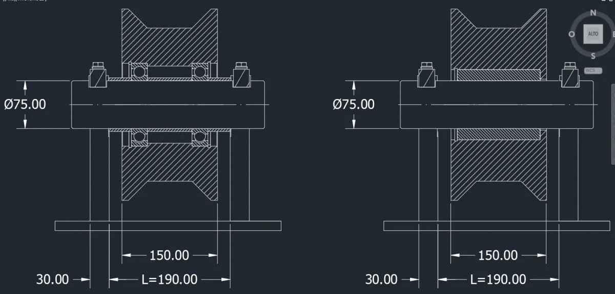
with the profile that I designed and since with the spacers that I have assembled the wheel will not be able to move axially, I therefore hypothesize that the drum at this point remains firm. on the other wheel instead I thought to mount a bushing that, sliding on the pin, indulges the expansions. That's because I don't like the idea of having a bearing on the pin at all.cadinpiedi, I don't know what you mean in the last part of the post where you're suggesting to hold your back, can you please explain to me?
Thank you!1658208029897.webp
 
I give you my impression:
- better shielded roller bearings.
- pin ø75 do ø80 c45 commercial chrome rectified.
- carpentry ears in a single piece or near the wheel, 20 mm are too many maximum 5 or better insert welded bushings so also increase the support of the pin.
-fermo tree with an axial stopper and anti-rotation also called din 15058 axis support.
everything is mounted by threading and pulling the pin so a head hole on both sides of the same for extractor would be comfortable.
I am quite certain that I would get a better system at a lower price.
in case you want to make the supports pin in two halves to facilitate the assembly and disassembly of the only wheel group, take the system above, including axial stop anti-rotation pin , and cuts in two not horizontal that not displaced it more but tilted of 29 degrees (radial in the tangence point of the drum ) ,coperchietti out to be able to dismantle it.
Then do all the calculations you want.
Ps:
Why 29 degrees? You can't do 30, so you can't make fun of the workshop.
pps :
at what temperature do you work presence of aggressive agents in the environment and in vapours/fumes?
ppps:
I see that the wheels have a plentiful containment in the sense of the drum axis (tilted plates), do you also have spins (forces) in that direction? If not reduce both the diameter and the thickness of the wheel and the iron (c45 + tempra induction ? nitro gaseous carburization ?) and the processing costs. Among other things, I think that you are forced to make a ring around the drum of at least 60 mm thick, perhaps even more if you consider the welds (proportion to the eye;) ).
Good morning.
thanks for the many tips! I can't understand the third point where you talk about carpentry ears though. 😓
the wheels I would have thought to realize them in 18ncd5 with surface treatment of cementing so as to avoid the wear given by the rolling and the axial movements given by the thermal expansions of the drum.
the distance between the wheel and the side of the support can not make it too small because I have to consider the expansions that are about 11 mm, and for questions simplicity constructive I will make only one type of support for both pairs of wheels.
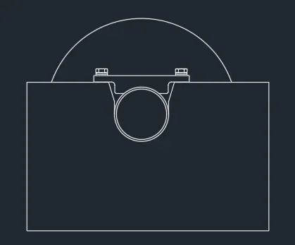
for mounting/mounting I thought of a support like what you see in the image. so that removing the stops I quickly manage to parade wheel and pin.1658208872165.webp1658208938372.webpthe support base is a welded box with sp. 30 plates on long sides and sp. 10 on the short side.
the thickness of the wheel came from the l/d report for the sizing of the bushing I intend to use.
 
on the other wheel instead I thought to mount a bushing that, sliding on the pin, indulges the expansions. That's because I don't like the idea of having a bearing on the pin at all.
I may have misunderstood your designs if not I do not understand how the drum expansions cause a shift of the wheel in the pivot axis direction. or not perhaps I understand.
I interpreted the axis of the drum parallel to the pin axis for which I would have a dilation on the length of the drum in the direction of the tilted shoulders of the wheel that at this point I would eliminate on the torque non-motor wheels in order to allow the shift of the drum on the same (the wheel let it stop on the pin), so you will have to widen the contact band on the drum, and a expansion on the diameter of the drum that not only
 
Last edited by a moderator:
expansions that are about 11 mm, and for simple construction issues I will make only one type of support for both wheels pairs.
where do you have 11 mm expansion on the pin? Are you sure there are so many you could have them on the diameter of the drum but they are still many, in fact they are many also on the length of the drum how far the drum is 6 meters?10 meters?
Tell me about dilation and then fix the pin with keystrokes on both sides?
 
Excuse me, you're right, 11 mm dilation I have on the length of the drum. the drum is 4 meters long and I have a delta t of 160°c. on the drum we will go to weld rings near the wheels, I attach a pdf.
My idea is that the drum dilating me slides the wheel with the bushing on the pin that I stuck with the sticks.
 

Attachments

But is that the first car you make of this guy?
I have seen some perhaps not exactly what you design, however I would make the ring around the drum much thinner with a thickness similar to the sheet (also to reduce the tensions during the expansions), I would lodge in the areas of ring 45/60 ° without air but not welded among them so that they can open slightly when the drum dilates.
wheels with shoulder only where you mounted the motor the wheels you want to slide on the pin I would flat make them so that the drum can slide on the wheels.
I'd put a spring tendicatena on the chain.
I can't understand the third point where you talk about carpentry ears though. 😓
Cattura.JPGthis is another application but more or less makes the idea.
the system you have done does not allow you to disassemble the drum wheel mounted if you want to do so you have to make a tilted cut of 30 degrees so that the wheel can parade tangent to the drum.
 
for me is the first, for the company the third and we are trying to improve the flaws of others.
I am aware that the disassembly of the wheel will have to be carried out in disassembled drum but the thing is acceptable.
I thought about it myself and thank you for all the ideas you're giving me! !
 

Forum statistics

Threads
44,997
Messages
339,767
Members
4
Latest member
ibt

Members online

No members online now.
Back
Top